
Improving Shear-Induced Imbalance in Hot Runner Systems
Even melt distribution and balanced filling to and across all cavities while avoiding restrictive mixers is possible with hot runner manifold construction that incorporates a melt rotation design.


Figure 5
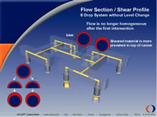
Figure 2
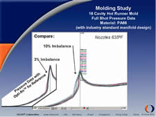
Figure 12

Figure 13b

Figure 11
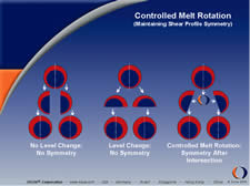
Figure 6

Figure 7
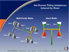
Figure 4
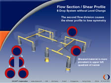
Figure 3
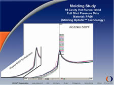
Figure 10

Figure 13a

Figure 14
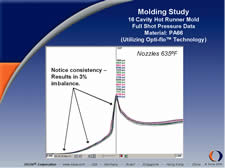
Figure 8
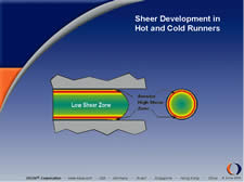
Figure 1. Figures courtesy of Incoe Corp.

Figure 9
Shear induced flow imbalance is recognized as contributing to a number of molding problems in multicavity molds. Uneven cavity filling is responsible for voids, core shift, inconsistent dimensional properties and other part defects.


Shear and Viscosity
In both cold and hot runner systems, shear rates are already known to be highest near the flow channel wall. As the molten plastic flows easily through the center of the channel, the material along the perimeter is dragged against the channel wall, causing a high rate of shear. Material first enters the flow channel and is deposited on the channel wall with the following material flowing through this layer and advancing to the front. At the transition of the layers, the moving plastic drags along the inside creating laminates of plastic flow, resulting in the center laminate to flow faster—generally described as fountain flow. The dragging of the material orients the polymer molecules in the direction of the flowing material or flow front. This condition, known as shear thinning, reduces the viscosity of the material. Since all plastic is non-Newtonian, the viscosity is directly affected by shear and temperature (see Figure 1).
Viscosity and Imbalance
When molten resin splits at an intersection—as in the case of the transition from the point of injection to the primary flow channel of a hot runner manifold—the annular ring of shear-thinned material does not remain symmetrical, but will be found more prevalent on the top side of the flow diameter on each side of the intersection (see Figure 2).
When the melt is divided at the secondary and tertiary runners, the sheared and non-sheared material is disproportionately divided. The result is unbalanced filling characteristics between the inside and outside cavities. In this example of an eight-cavity, single level design, the inside four cavities will fill before the outside four cavities since the shear-thinned material is of a lower viscosity and flows at a faster rate than the non-shear thinned material (see Figure 3).
In stack molding applications the cavities on the parting line closest to the point of injection are first to fill (see Figure 4).
Typical eight-cavity layouts produce two distinct flow groups. The inside four cavities—which fill first—are considered flow group one, while the remaining four outside cavities—which fill last—are considered flow group two. All cavities within a flow group will exhibit similar characteristics: part weight, material properties, etc. As the cavitation increases, the number of flow groups also increases—16-cavity system four flow groups, 32 cavities eight, and so on.
Imperfections from Imbalance
Many part defects can be attributed to flow imbalance. Cavities that fill first are typically heavier and larger than the remaining parts, potentially sticking in the mold and causing damage. Flash, sink and short shots are typical abnormalities that also can arise from uneven cavity filling. Dimensional variations between cavities also result due to uneven shrink rates and part weights. Additionally, uneven cavity filling contributes to core shift in certain applications.
Processing obstacles also become appar-ent from unbalanced filling. Cycle times and injection pressures are increased since cavities are not filling simultaneously, often requiring continual fine-tuning in an attempt to find the right balance between lashing certain cavities and under-packing others. Ultimately, productivity is reduced from longer setup times and higher scrap rates.
Addressing Imbalance
Prior to this recent awareness of the shear-thinning phenomenon, attempts to balance cavity filling were made by adjusting flow diameters, gate diameters and temperatures. While improved cavity filling could be achieved, it is generally not continuous. During later production runs, the temperature modifications made would not be sufficient to accommodate the new processing parameters—therefore once again establishing a new process was required.
Another trend in hot runner system design for improving balance in multicavity molds has been to incorporate full level changes at certain intersections. While balance is somewhat improved, this solution introduces still another shear distribution condition. Manifold designs incorporating full level changes direct the shear section of the flow profile to the outer cavities, which now fill first (see Figure 5).
Melt Rotation and Symmetry
By manipulating the orientation of the melt at flow intersections (called melt rotation), proportioned amounts of sheared and unsheared material can be distributed to all cavities, resulting in balanced filling. Melt rotation helps achieve symmetry at intersections, a necessary property of the shear profile so that when split, the shear profiles of the two resulting flows are consistent, and evenly distribute proportioned amounts of sheared and unsheared material (see Figure 6).
Applying melt rotation results in even distribution of the sheared and non-sheared material at each flow intersection (see Figure 7).
Prove It
Molders can perform a simple test procedure in their plant to see first hand the imbalances in their mold. The five-step process developed by Prof. John P. Beaumont describes the procedure and was covered on page 26 of the March 2004 issue MoldMaking Technology.
Cavity Pressure Analysis—Nylon 6/6
A molding study was performed using an industry standard manifold design and with a manifold utilizing melt rotation on a 16-cavity mold. Nylon 6/6 was used specifically for this experiment, as it requires more aggressive processing conditions and the material’s tendency to freeze at the gates.
Pressure transducers were equipped in every cavity. By measuring the pressure in each cavity independently, the readings would not only indicate the pressure within the cavity while filling, but also the moment when the cavity begins to fill. If the hot runner is not pressure balanced, frozen gates will experience different pressure, which causes some gates to open before others.
Molding full shots incorporating the optimized melt rotation manifold, the 16 pressure profiles are visibly consistent over the entire curve—indicating a balanced pressure condition within the hot runner system. The consistency also indicates that the frozen gates are breaking loose at the same time (the initial rise of pressure is consistent across all 16 cavities). (See Figure 8)
As part of the experimentation, the nozzle temperatures were reduced from 635ºF to 600ºF. The purpose was to measure the effect that the temperature change had on resulting cavity pressures during the molding process. In this case, the pressure profiles during filling remained consistent although a reduction of temperature was introduced. The opening of the frozen gates also appeared to remain consistent, despite the lower temperature. The illustration shows the comparison of the pressure profiles when molding at 635ºF and 600ºF (see Figure 9).
Nozzle temperatures were reduced further to 580ºF and the effects recorded. When compared to the pressure profiles attained when the nozzles were set at 635ºF, these pressure readings clearly demonstrate the effects of uneven opening of frozen gates (see Figure 10).
Molding full shots using an industry standard manifold design with nozzles set at 635ºF, the shear-induced imbalance created within the manifold results in obvious inconsistencies within the pressure profiles. The initial rise of the profiles appears consistent; however, the transducer readings begin to deviate toward the end of fill, indicating hydrostatic filling conditions (certain cavities filling before others). (See Figure 11)
When comparing the two sets of pressure profiles (industry standard manifold design and the optimized melt rotation manifold design; both with nozzles set at 635ºF), cavity-to-cavity pressure consistency can more readily be seen in the hot runner system that was using melt rotation technology. (See Figure 12.)
To complete the comparison, the industry standard manifold design was subject to the same reduction in temperature as the system containing melt rotation. The effects of the temperature decrease were immediately evident, as the pressure profiles show. The sporadic initial rise of pressure between each cavity indicates frozen gates not opening simultaneously. Therefore it can be concluded that the direct result of pressure differentials inside the hot runner system are due to shear-induced imbalance. Nozzle temperatures were then reduced further, which results in complete loss of the injection molding process. Gates open at various times and fill rates are vastly inconsistent. (See Figure 13a,b.)
To conclude the molding study, the nozzle temperatures of the hot runner system with the industry standard manifold design were individually manipulated to simulate a pressure balance. After considerable fine-tuning, an acceptable process was established. However it is important to note that in order to achieve the pressure balance for this system, the highest nozzle temperature was set to 680ºF and the lowest was set to 560ºF. This large difference in nozzle temperatures could possibly introduce variations of material properties from cavity to cavity. Differences in shrink rates and final part dimensions also could be affected. Of particular importance is the opportunity to reduce the cooling phase of the molding cycle, since it is dictated by the part or cavity that requires the most cooling; and, therefore is a significant factor to the overall cycle time. (See Figure 14.)
Benefits
It is well known in the injection molding community that adjusting nozzle temperatures can simulate balance within a hot runner system. However, the temperature variation needed to produce balance is quite large at times. While allowing the production of parts, a continuous and optimal molding environment is usually not achieved for long, and the goal of balanced cavity filling is compromised by longer cycles, complex and lengthy start-ups, increased scrap, inconsistent material properties and other molding defects. Using the optimized melt rotation hot runner technology, the melt delivery system is improved, opening the processing window and allowing the opportunity to improve efficiencies, reduce setup and cycle time, and reduce scrap.
Acknowledgements
Professor John Beaumont—Penn State University inventor of MeltFlipper technology and the "Five Step Process".


Related Content

Solving Mold Alignment Problems with the Right Alignment Lock
Correct alignment lock selection can reduce maintenance costs and molding downtime, as well as increase part quality over the mold’s entire life.
Read More
Forces and Calculations Are Key to Sizing Core Pull Hydraulic Cylinders
To select the correct cylinder, consider both set and pull stroke positions and then calculate forces.
Read More
Hands-on Workshop Teaches Mold Maintenance Process
Intensive workshop teaches the process of mold maintenance to help put an end to the firefighting culture of many toolrooms.
Read More
6 Ways to Optimize High-Feed Milling
High-feed milling can significantly outweigh potential reliability challenges. Consider these six strategies in order to make high-feed milling successful for your business.
Read MoreRead Next

How to Justify Your Hot Runner Purchase
Four questions to help with hot runner justification.
Read More
How to Use Continuing Education to Remain Competitive in Moldmaking
Continued training helps moldmakers make tooling decisions and properly use the latest cutting tool to efficiently machine high-quality molds.
Read More
Are You a Moldmaker Considering 3D Printing? Consider the 3D Printing Workshop at NPE2024
Presentations will cover 3D printing for mold tooling, material innovation, product development, bridge production and full-scale, high-volume additive manufacturing.
Read More