
Rapid Tooling for Sand Casting
Complex core system design and verification.


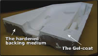
Figure 4. Negative with gel coat.
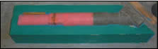
Figure 7. Half of core box with core.
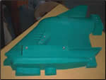
Figure 6. Final pattern.
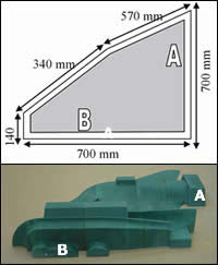
Figure 3. Retaining frame and positive of casing.
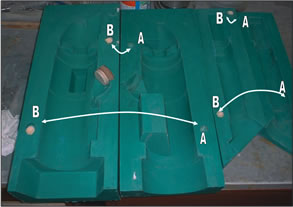
Figure 8. Final core boxes.
Figure 9. 3-D printing–based process chain versus CNC moldmaking for sand casting.
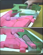
Figure 5. Fitting of the cores.
Figure 2. Process from start to finish.
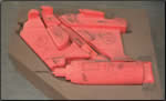
Figure 1. A half scale mock-up of the core system. Figures courtesy of Rapid Product Development Laboratory, Department of Industrial Engineering, University of Stellenbosch.
Tooling for sand casting can take as long as six months to produce. Three-dimensional printing (3DP) presents enormous potential for speeding the design and development cycle.
In sand casting the mold cavity is formed by means of a pattern, which is usually made of wood, metal, plastic or other material and has the shape of the part to be cast. The pattern is usually made oversized to allow for shrinkage of the metal as it solidifies and cools. Internal surfaces are determined by means of a core, a form placed inside the mold cavity to define the interior geometry of the part. To create the cores a core box needs to be built, which is basically the negative of the core itself.
The conventional path to a sand casting core is a laborious, time-intensive process. The various steps of creating and verifying prototype tooling can take up to a few weeks. In this article it will be shown through a case study that by contrast, the 3-D printing process can produce cores and patterns in a few days. The patterns and cavities produced in this way are of equivalent accuracy, and have properties that are virtually identical to tooling created with conventional methods.
Development and Realization of Prototype Tooling for Sand Casting
A Case Study
A process chain using 3DP as an instrument for generating the physical model of the required component in end use material was developed for making tooling for sand casting. Essentially the method relies on printed parts as patterns for creating bridge tooling using sand mixed with epoxy as a low-cost backing medium. This process chain was developed for producing large metal components such as gearbox housings, and demonstrated by making tooling for a marine engine gearbox and drive train enclosure, respectively. Five fully functional, aluminium components were required for testing and marketing this design concept.
|
Table 1. Table courtesy of Rapid Product Development Laboratory, Department of Industrial Engineering, University of Stellenbosch. |
|||
| Section |
Total Build Time (hours) |
Number of builds needed | Remove and clean (hours) |
| Casing Right |
33.40
|
5
|
10
|
| Casing Left |
28.75
|
5
|
10
|
| Growth times of the different sections. | |||
At first a half scale mock-up of the pattern and core system was developed and printed (step 3.3 in Figure 9). This facilitated discussion and planning of the core system—ensuring that sufficient support was provided for all cores, checking the wall thickness, deciding on the core layout and the number of required cores (Figure 1). This is invaluable in bringing the designers, pattern maker and foundry personnel together as a concurrent engineering design team. Many potential problems can be ironed out early in the design phase by adopting this kind of design for manufacture approach. It further facilitates quotation and planning by the foundry.
The case study discusses the development of the left- and right-hand patterns and the necessary core boxes for the gear casing. Because of the size of the gear casing a large number of parts were grown in sections. This is due to the limited size of the 3-D printer’s work platform (200 x 250 x 200 mm). Most of the time more than one section can be grown at once in the bin of the 3-D printer. The process from the CAD model to the delivery of the core boxes and patterns can be seen in Figure 2.
Building the Patterns and Core Boxes for the Gear Casing
Building the Patterns
After slicing the 3-D CAD model accordingly, the sections have to be fabricated in the 3-D printer. The building orientation is selected and the sections are placed to fit in the building platform of the printer. Table 1 gives some details regarding the time required for this particular development.
The drawings for each part are studied and the critical dimensions are checked. The sections are then put into the 70°C (158oF) oven for short intervals until they shrink to the desired size. Then the builds are infiltrated with wax to strengthen them.
The assembled sections can be seen on the right hand side of Figure 3 just after they were glued together with glue wax and sized to specifications. A retaining frame is built from plywood sheets fitted together with screws. The part needs to fit tightly to both sections marked “A” and “B” as can be seen in the Figure 3. A minimum clearance of 20 mm is further needed between the rest of the part and the edges of the box. The negative is created by applying a backing medium of sand and resin.
After the part is placed into the retaining frame, it is brushed with Ramwax and then sprayed with a mold release agent to make it easier for the part to be removed afterward. Now the part and floor of the box are painted with a white gel coat. Even strokes are applied, making sure that the whole surface of the part and the floor of the box are covered. The coating takes approximately 30 minutes to set, but the time may vary due to different room temperatures.
To provide the backing medium, silica (sand) is mixed with a mixture of resin and hardener. A thin layer of the resin mixture is applied to the gel coat to make it stick to the silica mixture.
The model is chiseled out of the backing medium after it has hardened. The casing negatives weigh approximately 79.37 lbs (36 kg) each. The backing medium with the gel coating on top now forms the negative as can be seen in Figure 4.
By this time in the process the cores are already built in much the same way as the model for the positives. The cores also are built in sections, which are then mended together and shaped to the desired size. The cores are fitted individually at first and made sure that the correct material thickness will be achieved between them and the negative. Afterward the cores are fitted as can be seen in Figure 5 and their dimensions are checked.
To create the final pattern a more rubbery green gel coat is used. The gel coat is applied on top of the part, box floor and box sides. Then a thin coat of the resin mixture is painted over the green gel coat. Silica (sand) is mixed with a mixture of resin and hardener. The mixture is compacted into the retaining frame and then smoothed at the top. A ready pattern can be seen in Figure 6.
Building the Core Boxes for the Cores
To develop the two halves of the core box, it has to be planned precisely where the split needs to be made. A wooden joint board is then made around the split line so that one half of the core box can be made first.
The same green gel coat is applied as for the casings. The core and box need to be waxed with Ramwax first. The resin mixture is now applied to make the sand mixture stick to the already applied gel coat. After the sand mixture has set and the wooden box is removed, the part looks as seen in the picture in Figure 7.
After the backing medium has cured the wooden box is removed and the core box is separated on the split line. The core is now removed and the two halves are then cleaned (Figure 8). The locaters “A” fit into the locating holes “B” in order to align the core box halves to each other.
Time and Cost Study
A detailed time study showed the clear superiority of 3-D printing compared to traditional processes of making tooling. It took only 62 hours to print the cores, while an experienced toolmaker would spend some 180 hours in achieving the same result working with traditional methods.
Not only is this almost a third of the time, but attention to other jobs or processes can be given while the printer is building the related parts. The development of the patterns, once the negatives were done, took only seven working hours—excluding the curing time, which is usually scheduled to be nonworking hours. An estimated 60 percent cost reduction was further achieved by using layer manufacturing techniques.
Conclusion
This case study shows that 3-D printing can dramatically decrease the development time of tooling for sand casting at reduced cost. The time and cost depend to a large degree on the object’s size, purpose and different post-processing techniques required.
The newly developed process chain is compared to the current approach of machining the tooling directly using the CNC option (Figure 9). Beside the time savings, an additional advantage is the ability of 3DP to test the core system and perform systematic checks along the process chain as required. The full scale check (step 3.9)—involving eight printed cores—specifically allows scrutinizing of the wall thickness and core prints, while CNC machining of the tooling precludes these tests.


Related Content

How to Use Thermal Management to Improve Mold Cooling
A review of common mold cooling issues and possible solutions, including 3D printing applications.
Read More
Large Hybrid Steel Insert Solves Deformation, Dimensionality, Cycle Time Problems
DMLS printers using metal additive powders selected by Linear AMS to produce high-quality, accurate, consistent 3D-printed mold components with certification and traceability.
Read More
VIDEO: How can 3D Printed Tooling Improve Injection Mold Venting?
Proper venting is one of a mold builders toughest challenges as molders struggle to keep vents free flowing in production. Learn how to apply 3D printing to mold venting and the benefits of additive venting inserts.
Read More
Variable Density-Coated Tool Steel for High-Wear Molds
A mold builder can have an abundance of venting and fully dense solid areas in steel by using variable density sintering to eliminate gas trap defects in high-wear molds.
Read MoreRead Next

Thought to Part: Rapid Manufacturing
An example where rapid product development and direct digital manufacturing can work.
Read More
How to Use Strategic Planning Tools, Data to Manage the Human Side of Business
Q&A with Marion Wells, MMT EAB member and founder of Human Asset Management.
Read More
How to Use Continuing Education to Remain Competitive in Moldmaking
Continued training helps moldmakers make tooling decisions and properly use the latest cutting tool to efficiently machine high-quality molds.
Read More