
Mold Material: Electroformed Composite Molds
Could a mold with electroformed composite inserts save you money?


Following the lead of Japanese automotive companies, injection molders worldwide have begun to realize that the high thermal conductivity of aluminum molds—and the shorter cycle times it enables—is often worth the cost of shorter mold life.
Aluminum production tooling is being more widely embraced, though this compromise remains a bitter pill to swallow for many. Especially conflicted are those molders with very high-volume requirements, or those who mold with aggressively abrasive resins (e.g. glass-filled PVC). These molders have a hard time reconciling their need to shorten cycle times with the cost and logistical headaches of constantly replacing tooling—because of the rapid wear and oxidation of relatively soft aluminum tooling. Sometimes even small errors in predicting the longevity of aluminum tooling or expected cycle time reduction can put a molder unexpectedly on the wrong side of the cost/benefit equation, when contemplating this choice.
Now there is another option to consider—an alternative that is made neither of aluminum nor fully of traditional tool steel; molds that are efficient heat exchangers or rapid exchangers of heat made by a patented process. This article will take a look at the tool life and cycle time expectations, thermal conductivity, and conformal cooling channels of these molds.

Table 1 courtesy of ConforMAL, Inc.
Breaking Down the Process
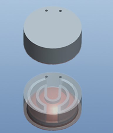
Two views of the same insert's underside, showing the coolant in and out openings. One view shows the steel blank as semi-transparent to reveal the internal cooling circuit.
How does this process avoid the usual trade-off between cavity wall hardness and high thermal conductivity? The mold cavity is actually a composite—comprising a thin, hard nickel alloy shell forming the cavity wall itself, which is backed by a thicker layer of pure copper. This copper layer is in direct contact with coolant flowing through the conformal cooling channels. Though the nickel shell is already more thermally conductive than tool steels, it is the copper that is the key to the thermal efficiency of molds made by this process.

A nickel alloy/copper composite electroform above a steel blank roughed out to accommodate it, with the cooling circuit already milled into the blank (shown in blue).
The nickel-copper composite is made by electroforming, which is an additive electrodepositional fabrication process with a long history of specialized applications in moldmaking. Metal is plated onto a conductive mandrel that serves as a pattern for the resultant electroform, from which it is later separated. In this case, the nickel alloy is plated directly onto the mandrel and copper is plated atop the nickel alloy.
The advantageous thermal characteristics of electroformed mold cavities are nothing new. Slush molders, thermoformers and rotational molders have long taken advantage of the thermal conductivity of electroformed molds, but a process for making electroformed injection molds with integrated cooling in a cost-effective manner is somewhat novel.
More than a decade ago, companies experimented with similar composite electroformed mold cavities. They had the right idea to that extent, but they brazed copper tubing onto the electroformed shell to create the conformal cooling channels, much like thermoform toolmakers sometimes do, and then over-plating more copper. This was a slow and labor-intensive process.
There were problems backing the electroformed cavity to form a mold insert. A proprietary, metal-filled, polymeric compound was used to make up the bulk of the insert, which met with limited success. In all, it was too protracted a process to be economically viable.
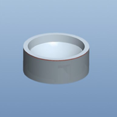
The assembled insert after EDM and bonding.
In contrast, this new patented process, takes advantage of an old, but little-known, trick of using the copper backside of the electroform as an EDM electrode to sink the electroform into a conforming pocket in a block of tool steel. The cooling channels are simply milled into the tool steel at the interface between the copper and the steel. Because the electroform is relatively thin and inherently follows the contours of the cavity, the resulting cooling channels are automatically conformal to the cavity’s shape.
The electroform is then bonded to the tool steel block (by one of several means) and the assembly is brought to finished dimensions as one piece. The resulting mold insert has a high thermal conductivity envelope surrounding each cavity, which virtually sucks heat from the cavity walls. It creates a very thermodynamically advanced mold.
Though the process offers great advantages for injection molding, it is also suitable for making blow molds, thermoform tools and resin transfer molds. There is a size limitation imposed by the EDM portion of the fabrication process. It’s possible to electroform large molds, but the trick is to be able to use EDM to sink them into a steel block. This puts a practical limit on the size of the insert that can be made—it must fit into the EDM dielectric tank.
Determining the Application and Benefits
Whether this is a good option for your shop needs to be evaluated on a case-by-case basis. There are geometrical limitations of the electroforming process and not every application is a good fit. For example, deep recesses and holes in a mandrel are problematic to electroform.
Many applications could benefit from the thermodynamic efficiency of these molds, especially those that are not well served by 3-D freeform fabrication methods for creating conformal cooling. This tooling is a good fit for optical applications—such as automotive lighting lenses or laser scanner reflectors.
Assuming the geometry can be successfully electroformed, the cost/benefit analysis revolves around the cycle time reduction anticipated. This is where mold cooling simulation software proves its worth. With most professional simulation software packages on the market, it’s possible to model an electroformed composite tool as well as its traditionally designed counterpart.
Though the resultant predicted cooling times may not be absolutely accurate, they should be a good guide as to the expected difference in cooling times (and cycle times). This cycle time difference can be used to back-calculate the run time reduction for a specified run. The hours saved/run multiplied by the hourly running costs of the press gives an anticipated cost savings per run. Let’s look at a hypothetical example.
Example: An injection molder runs a two-cavity mold. If he needs to make 500,000 parts and the mold runs a 34-second cycle, he can make these parts in 14.1 weeks (assuming 24/7 operation). Also assuming press operating costs of $65/hour, this will amount to $153,472 for the run. If, however, through more efficient cooling of an electroformed composite mold, this part can be molded five seconds faster (a roughly 15-percent cycle time reduction), the 500,000 parts can be molded in just under 12 weeks, at a running cost of $130,903. This saves the molder $22,569 on the run.
This means that even if the mold were to cost $10,000 more to be built with electroformed composite inserts, the molder would recoup those costs in less than 12 weeks, plus save an additional $1,000 dollars a week, to boot! The molder would save another $22,569 for every 12 weeks he continues to run the mold. What’s more, because the mold’s cooling is more uniform, part distortion is reduced, so the scrap rate may be lower. Table 1 summarizes this example.
Summary
Could you save money by using a mold with electroformed composite inserts? Model the cooling. You may be surprised how quickly these thermodynamically-advanced electroformed composite molds can pay for themselves.


Related Content

How to Select a Mold Temperature Controller
White paper shares how cooling channel analysis, which collects maximum pressure drop, total flow rate and heat dissipation, eases the performance evaluation of mold temperature controllers.
Read More
MoldMaking Technology's Most-Viewed Content 2022: Products
MMT shares the five top-viewed technologies, equipment and services of 2022 in each Engineer, Build, Maintain and Manage tenet based on Google Analytics.
Read More
It Starts With the Part: A Plastic Part Checklist Ensures Good Mold Design
All successful mold build projects start with examining the part to be molded to ensure it is moldable and will meet the customers' production objectives.
Read More
How to Manage Wall Thickness Changes in Your Mold Design
To ensure even filling and cooling, consider wall section transitions, corners and fillets, ribs and bosses, lip and rim designs and CAE flow simulation software.
Read MoreRead Next

Cost Savings for Mold Materials: Consider the Details
Ways to reduce costs that are not related to the price per pound of the mold material.
Read More
Reasons to Use Fiber Lasers for Mold Cleaning
Fiber lasers offer a simplicity, speed, control and portability, minimizing mold cleaning risks.
Read More
How to Use Strategic Planning Tools, Data to Manage the Human Side of Business
Q&A with Marion Wells, MMT EAB member and founder of Human Asset Management.
Read More