
Make Mold Cooling Easy and Effective
Strategies for designing an effective cooling system with less time and effort.
Simulating plastic fill with molding analysis will show the expected temperature of the plastic part throughout the molding process. Images courtesy of Cimatron Technologies.
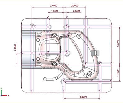
CAD identifies the water line and issues a warning if it gets too close to core (or other mold components) outer surfaces.
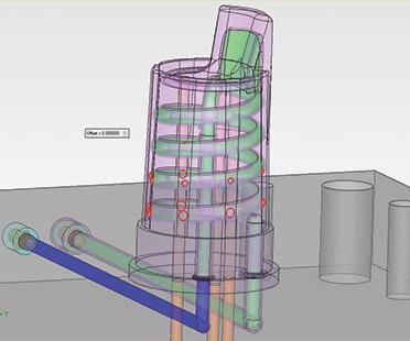
Here, CAD performs a safety distance check on a conformal cooling channel. The red marks depict where the channel comes closer than 0.050 inch to the part.


When it comes to injection molds, the importance of an efficient cooling system cannot be overemphasized. A reduction of just one or two seconds in cooling time can lead to as much as a 10- to 20-percent increase in the production rate. That alone could directly affect the profitability of the job. However, saving time is not the only benefit of a cooling system.
Controlled cooling of the entire plastic part is vital to the preservation of its dimensional stability and mechanical properties. Properly cooled parts are less likely to warp, get stressed or be brittle. It is easy to see why a well-designed cooling system is a key component of a well-designed injection mold, leading to the profitable production of high-quality parts. Here are some tips to help you design an effective mold cooling system, while reducing design time and effort:


Decide on the most critical components to cool. In most tools with inserted cavities, the cavity blocks and slides are the only components in the tool that require cooling lines. While the surrounding plates will get hot, adding cooling into them will not contribute much towards the ultimate goal of removing heat from the plastic part.
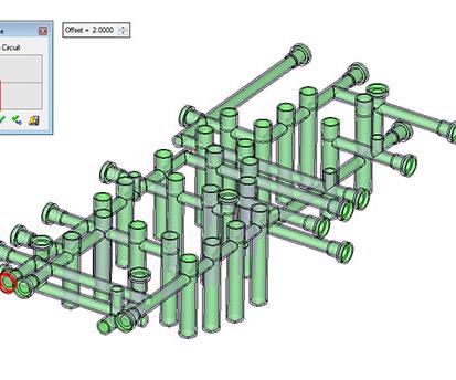
In molds with individual cavity blocks, the cooling design typically can be viewed as a circuit. It will have an inlet and an outlet, and will trace a path through the block. The circuit should be close enough to the part to effectively remove the heat, but not so close as to risk drilling holes into any of the mold features.
Make smart material choices. Items like core pins and lifters are often too small to get any effective cooling inside them. If you are concerned about removing heat from small inserts, you may want to use material with a high rate of thermal conductivity for these components. Aluminum and bronze alloys have much higher thermal transfer rates than steel and can be very useful for pulling the heat out of the plastic and towards the cooling circuits.
Create an effective water circuit. Creating a water circuit with a thorough path around the part is the most important consideration for cooling effectiveness. Bending the circuit around the part contributes to a turbulent water flow, which helps to pull the most heat from the steel. At the same time, be careful not to make the circuit too long and complex, which would cause the water temperature to rise to the point that it diminishes the cooling effect. Generally speaking, you want to keep the water temperature no higher than 2-3°C above the entry-point temperature.
Speed up design using catalog parts. Once the circuit is designed, get the plugs and other water components in place. Using standard components from 3D catalogs can save you as much as 80 percent in design time. All you need to do is pick the part and drop it into your design.
Adjust your strategy when dealing with large parts. A different type of strategy often is applied to cooling very large parts or typical automotive tools where left- and right-hand parts are both required. With large core plates that measure 6 feet or even longer, a cooling system made of long winding circuits will not be effective in pulling the heat out of so much plastic. Instead, molds of this type are usually designed with straight-through channels. Each channel is a circuit unto itself and can be drilled to a depth that comes very close to the part, often with baffles that serve to direct the water up into the higher portion of the mold.
Ease the design of baffles and bubblers. To increase cooling efficiency, baffles and bubblers should be custom-fit to each area. Yet, custom-fitting hundreds of baffles and bubblers can drain a lot of design time.
A system that allows for automated selection of baffle and bubbler length and adds these directly to the bill of materials can cut the time spent on this task from hours to minutes.
Use built-in analysis. Even the best designer can occasionally make a mistake. Look for a system that can analyze the completeness of a water circuit. Simulating the water flow provides an added measure of assurance that your cooling system will work as intended.
Simulate plastic fill. Take it a step further by simulating the plastic fill with molding analysis. This is a sophisticated process that will animate the plastic flow through the part and highlight problem areas such as air traps and weld lines. On top of that, it can analyze the cooling channel design and predict the temperature of the plastic part throughout the molding process. Running a simulation can identify numerous potential cooling issues, such as hot spots on the part, long cooling times or even warping.
Use CAD software built for moldmaking with specific cooling functions. A smart CAD system can automate many of the tasks involved in the creation of the cooling circuits, greatly reducing the time spent and the potential for human error. Recognizing that the lines are designed for water, the software will automatically attach intelligent rules to catalog parts. For example, it recognizes that a 1/4-NPT plug is appropriate for a 7/16-drilled line, so these components automatically fall into place for any channel selected.
In addition, software that automatically cuts any required pocket or thread when a catalog component is added to the design will significantly minimize repetitive tasks.
Consider conformal cooling. Many injection molders have already discovered the advantages of conformal cooling. Transcending the limitations of straight-line designs, conformal cooling channels closely follow the shape of the cavity and core to better reach hot spots and promote temperature uniformity. To make conformal cooling part of your shop’s repertoire, you need access to 3D printing, as well as a CAD system that can design and analyze circuits that are more than a series of straight lines.
3D Systems - Cimatron Software


Related Content

Tolerancing in Mold Design, Part 2: Using GD&T to Address Conventional Tolerancing Issues
Mold designers can achieve a single interpretation of workpiece functionality when following the American Society of Mechanical Engineers Geometric Dimensioning and Tolerancing standard.
Read More
Tolerancing in Mold Design, Part 1: Understanding the Issues of Conventional Bilateral Tolerancing
Mold designers must understand the location, orientation and form limitations of conventional tolerancing before changing to another dimensioning system.
Read More
How to Manage Wall Thickness Changes in Your Mold Design
To ensure even filling and cooling, consider wall section transitions, corners and fillets, ribs and bosses, lip and rim designs and CAE flow simulation software.
Read More
The In's and Out's of Ballbar Calibration
This machine tool diagnostic device allows the detection of errors noticeable only while machine tools are in motion.
Read MoreRead Next

Unique in Every Way
This moldmaker transformed its current processes with a multi-function, universal CAD/CAM solution.
Read More
How to Use Continuing Education to Remain Competitive in Moldmaking
Continued training helps moldmakers make tooling decisions and properly use the latest cutting tool to efficiently machine high-quality molds.
Read More
Are You a Moldmaker Considering 3D Printing? Consider the 3D Printing Workshop at NPE2024
Presentations will cover 3D printing for mold tooling, material innovation, product development, bridge production and full-scale, high-volume additive manufacturing.
Read More