
How to Exceed the Limits of Your Toolpaths
A moldmaker’s ability to reduce machining time is not limited by his machine tools or cutting tools, but rather by the toolpaths that drive them.


Figure 4: A tool reaches full engagement (180° TEA) whenever it encounters a corner angle that is less than or equal to its straight-line engagement angle. In this case, both the straight-line engagement angle and the angle of the corner equal 113.58°.

Figure 2: When cutting in a straight line, a stepover value of 30 percent of the tool diameter equates to a 66.42-degree tool engagement angle.

Figure 6: When a tool programmed at a 10 percent stepover (36.87° TEA) encounters an inside corner of 90°, the TEA increases by 90°, to 126.87°.

Figure 1: When cutting in a straight line, a stepover value of 70 percent of the tool diameter equates to a 113.58-degree tool engagement angle. Figures courtesy of Surfware, Inc.
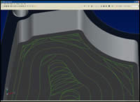
Figure 7: To machine with uncompromised parameters requires toolpaths that have no sharp corners, regardless of the shape of the part, and that dynamically manage the tool’s engagement with the material, keeping it at or below a user-controlled threshold.
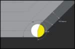
Figure 3: When a tool programmed at a 70 percent stepover (113.58° TEA) encounters an inside corner of 135°, the TEA increases by 45°, to 158.58°.

Figure 5: When cutting in a straight line, a stepover value of 10 percent of the tool diameter equates to a 36.87-degree tool engagement angle.
Existing high-speed machining technology for rough milling is founded on an unnecessary compromise. In order to increase two of the primary machining parameters—spindle speed and feedrate—two other primary parameters—depth-of-cut and stepover—are decreased. While the machine certainly moves faster, material removal rates fall far short of what they could be. This is entirely due to the fact that all toolpath algorithms since the inception of numerical control are fundamentally flawed, and the specialized high-speed milling algorithms that have emerged over the past decade contain the exact same flaws.
What is needed is a toolpath algorithm that doesn’t require a compromise of any of the machining parameters, but rather enables them to be used in whatever combination yields the fastest material removal rates and longest cutting tool life. With such a toolpath engine, tools could be driven at faster feeds and speeds along with deeper depths-of-cut and larger stepovers, significantly reducing cycle times.


The fundamental limitation of material removal rates is the inability to control the cutting tool’s engagement with the material. If the tool engagement angle (TEA) with the material is not constant, then machining parameters must be set to a level that is acceptable—does not cause catastrophic tool failure—when the TEA is at its highest. In non–high-speed milling methods, the depth-of-cut and stepover are typically kept at the desired values, but the spindle speed and feedrate are reduced. HSM methods merely flip-flop the compromised parameters. Is high-speed milling a better method of machining? Perhaps, perhaps not. Is it an ideal method of machining? Absolutely not.
A Better Understanding of Toolpath Generators
In manual milling, it is impossible to move a cutting tool through material, using crank handles, on a path that keeps the TEA constant, or even remotely so. Thus, the inability to control the TEA is not a numerical-control milling problem, but rather a general milling problem. With the advent of numerically controlled milling machines, however, it immediately became possible to drive a cutting tool through material in an engagement-controlled manner. The linear and circular interpolation capabilities of these machines made it so. All that was needed was a toolpath generator that would leverage these capabilities to revolutionize the material removal process. Unfortunately, all toolpath generators essentially do little more than automate manual milling methods. Consequently, a golden opportunity to increase productivity has gone unrealized.
To better understand the shortcomings of current toolpath generators, it is helpful to analyze some basic milling dynamics. These dynamics are a fact of life with every toolpath that has ever been generated, and, as will be seen, are clearly detrimental to the machining process. Yet the machining industry has not only ignored these dynamics, but openly accepted the problems they cause. These basics are not taught to beginning machinists, to the point that the reader may find them surprising. Perhaps this is because there was believed to be nothing that could be done about the problems.
Basic Milling Dynamics
There is a relationship between a programmed stepover and a tool engagement angle. For example, a programmed stepover of 50 percent of the diameter of the tool equates to a 90-degree TEA. A 70 percent stepover equates to a 113.58° TEA (see Figure 1). And a 30 percent stepover equates to a 66.42° TEA (see Figure 2). For any given stepover value there is one—and only one—corresponding tool engagement angle. But this is only true when cutting in a straight line or along a constant radius with a constant radial depth-of-cut.
It is well known from experience that when a tool encounters an inside corner, the TEA increases. What is perhaps not commonly known is that there is a simple formula to calculate the amount of this increase: A tool’s engagement angle with the material will increase in an inside corner by the supplement of the angle of the corner (180° - the corner angle).
Therefore, when a tool programmed at a 50 percent stepover (90° TEA) encounters a 90° corner, its engagement doubles to 180°. 90° + (180° - 90°) = 180°. If the corner is 135°, the engagement angle increases by 45° to 135°. 90° + (180° - 135°) = 135°. So, when a tool programmed at a 70 percent stepover (113.58° TEA) encounters an inside corner of 135°, its engagement angle increases by 45° to 158.58° (see Figure 3). It follows, then, that a tool reaches full engagement (180° TEA) when the angle of the inside corner is less than or equal to the straight-line TEA (see Figure 4).
The negative consequences of machining inside corners are well known. The loading and unloading of the tool in these corners is what causes the groaning and screeching that are indigenous to life in a machine shop. Since these are the moments of highest stress on the cutting tool, feedrates and spindle speeds must be set low enough to ensure the tool’s survival in these corners. As discussed, the typical high-speed milling process increases the feeds and speeds, but decreases the depth-of-cut and stepover. However, an interesting phenomenon occurs when the stepover is reduced: Although the numerical engagement value in a corner may be less with a smaller stepover than with a larger one, the percentage increase in TEA is greater with a smaller stepover than it is with a larger stepover.
When a tool programmed at a 10 percent stepover (36.87° TEA; see Figure 5) encounters a 90° inside corner, its TEA increases by 90°, to 126.87° (see Figure 6). This is a 244 percent increase in TEA, compared to a 100 percent increase in the same corner for a tool programmed at a 50 percent stepover. With a cutter of three or more flutes, this TEA requires two flutes to be engaged with the material simultaneously, increasing the power draw on the spindle. In sharper corners, the TEA can easily reach 180°, full burial, which is an increase in TEA of 388 percent. Any tool with more than four flutes now has at least three of those flutes simultaneously engaged with the material. So the seemingly light cuts associated with high-speed milling are not light at all whenever an inside corner is encountered, which is obviously extremely common. The engagement angle that correlates with the programmed stepover is violated severely and repeatedly.
What this means, of course, is that even with the smaller stepovers associated with high-speed milling, the tool is under a greater load than expected. The tool is clearly feeding slowly enough to be able to withstand the excess load in the corners, which means that the tool is being used inefficiently when not buried in a corner. The increased machining load in corners continues to limit feedrates, even with smaller stepovers and depths-of-cut.
Further, decreasing the stepover and the depth-of-cut increases the number of instances in which a spike in the engagement angle occurs. If a stepover value is cut in half, the number of cuts in the X-Y plane is doubled. Therefore, the number of instances of excess engagement is doubled (or essentially so, depending on the specific shape being machined). If the depth-of-cut is reduced by half, there are twice as many cuts in the Z direction, and the number of instances of excess engagement is doubled again. So if the programmed stepover is reduced by a factor of five, from 50 percent to 10 percent, for example, and the depth-of-cut is reduced by a factor of four, the number of times that the machine tool and cutting tool are subjected to adverse machining conditions increases by a factor of twenty.
Another hallmark of high-speed milling algorithms is the introduction of small-radius arcs in the toolpath between segments that would otherwise not be tangent-continuous. While this removes the need for the machine to come to a complete stop in order to change directions, and enables the program to stay in “high speed mode,” it does little to lessen the increase in TEA. In the above example of a 10 percent stepover, adding a .010 radius (a commonly used value in high-speed milling algorithms) in a 90° corner, and assuming a one-inch diameter cutter, reduces the engagement angle from 126.87° to 124.91°, a negligible amount. Adding larger radii reduces the TEA, but this leaves more uncut material in the corners that must be dealt with, and typically causes toolpaths to collapse on themselves just a few cuts from the boundary, leading to several other problems. And, for a given radial depth-of-cut, the TEA is always greater on an inside arc than it is on a straight, regardless of the radius of the arc. Further, the way these arcs are typically utilized is actually detrimental to the machining process, forcing feedrates to be reduced further still.
When a tool traverses an inside corner-radius, the periphery of the tool, where the chips are separated from the material (assuming a climb milling direction), is feeding faster than the center of the tool. The difference in speed is a simple function of the radius of the tool and the radius of the toolpath corner. For example, in a corner that is equal in radius to that of the cutting tool, the effective feedrate at the periphery of the tool is double that of the programmed feedrate. If the toolpath radius is half that of the cutting tool radius, the effective feed is triple the programmed feedrate. The larger the difference in these radii, the greater is the feedrate disparity. The numbers can be alarming. When a three-inch diameter shell mill, for example, traverses a .010” toolpath radius, the effective feedrate at the periphery of the tool is one-hundred-fifty-one times greater than the programmed feedrate. Using high feedrates without making adjustments for such corners is a recipe for disaster. This is yet another reason why material-removal rates with existing high-speed milling methods are not what they could be.
But what if there were a toolpath engine that didn’t require compromises in the machining parameters? If the TEA were under control, load spikes in corners would cease to exist. With no load spikes, larger stepovers could be used at even greater feeds and speeds. Machine tools and cutting tools would finally be free to perform up to their capabilities, rather than be limited by the toolpaths that drive them. This would require a toolpath that dynamically managed the tool’s engagement with the material. If the same toolpath engine automatically manipulated the programmed feedrate such that it was always maintained as the effective feedrate, machining parameters could be increased further still. Such a toolpath engine is what moldmakers need in their shops to improve machining operations.
Tool Engagement Control
Moldmakers need to search out a toolpath engine that generates toolpaths that effectively have no corners, regardless of the shape of the part being machined, and that maintain the TEA at or below a user-controlled threshold (see Figure 7). Doing so eliminates all of the problems discussed above. The user will be able to enter the exact same machining parameters as before, but the specified stepover value will be converted to a tool engagement angle, and that angle will never be exceeded as the toolpath is calculated. Alternatively, the user may enter the desired TEA directly.
With such a toolpath generator much more aggressive machining parameters can be used. Larger TEAs can be specified that significantly reduce the number of cuts and resulting excess toolpath length, yet don’t come close to the extreme engagement angles inherent to existing toolpath algorithms. Not only can larger TEAs be used, but the spindle speeds and feedrates can be increased even further, up to the capabilities of the machine tool and cutting tool in use. The toolpaths will look entirely different from traditional toolpaths (again see Figure 7), but this is a logical requirement if the fundamental flaws of traditional toolpaths are to be circumvented.
With traditional toolpath engines, the toolpaths themselves are what limit the material removal rates; the severe spikes in tool load require that machining parameters be kept well below what the hardware is capable of. With the right toolpath generator, recommended cutting feeds and speeds are obsolete. Surface speeds can be increased significantly, and feed-per-tooth recommendations can be easily doubled, and often tripled, with no damage to the cutting tool. And the machine will run smoother and quieter than with traditional toolpaths.
This is true in all materials that were tested with this new toolpath generator—from 6061 aluminum to 62 HRC materials—with deeper depths-of-cut and larger stepover values than remotely possible with traditional toolpath algorithms. Since the amount of material encountered is never above a known threshold and the programmed feedrate is automatically maintained as the effective feedrate, post-processing feedrate optimizers are entirely unnecessary. Since excess material is never encountered, there is never a need to slow down. The toolpaths are inherently optimized. The resulting savings in cycle time are impressive. Depending on the shape being machined, the toolpaths from this generator can remove the same volume of material anywhere from 20 percent faster to several times faster than existing toolpaths. And since the load on the tool is accurately managed, cutting tool life is extended significantly, even with the shorter cycle times.
Since the benefits of this new technology in toolpath generation are derived solely from driving cutting tools in a more intelligent manner, they can be realized on any existing hardware. Shops can immediately become more productive simply by using a new toolpath generator that meets the aforementioned criteria, the cost of which pales in comparison to investing in expensive, sophisticated machining hardware. But since these toolpaths will perform up to the capabilities of any machine tool or cutting tool, any investment in upgraded hardware will be rapidly rewarded with even further reduced machining times.
Improving the Bottom Line
Moldmakers face many challenges in today’s competitive environment: global competition; CAM software that is not easy to use; a perceived diminishing skill level in the workforce; dealing with non-native data, potentially from multiple sources; not being well trained on or fully utilizing their current software; and, the need to improve supporting processes, just to name a few. And certainly most moldmakers are faced with one or more of these challenges, to one degree or another. But one thing all moldmakers must ultimately do well is cut metal. So perhaps the greatest problem they face is one they were not aware they had: Their ability to reduce machining time is not limited by their machine tools or cutting tools, but rather by the toolpaths that drive them. Machining time is much more costly than programming time or computing time, and saving time here can make any shop more competitive and contribute to a much improved bottom line.
It has been said that there are no new frontiers in machining and that metal can only be cut so fast, and improvements must therefore be sought out elsewhere in the overall process. But a new toolpath engine challenges those assertions. The definition of high-speed milling has changed. High-speed milling no longer means smaller stepovers and shallower depths-of-cut. With the right toolpath generator, no machining parameters need be compromised, and metal can now be removed at rates never before possible, which should benefit every moldmaker.


Related Content

The In's and Out's of Ballbar Calibration
This machine tool diagnostic device allows the detection of errors noticeable only while machine tools are in motion.
Read More
Solving Mold Alignment Problems with the Right Alignment Lock
Correct alignment lock selection can reduce maintenance costs and molding downtime, as well as increase part quality over the mold’s entire life.
Read More
Control Helps Push the Limits of Five-Axis Micro Mold Machining Accuracy
Toolmaker quickly meets the demands of critical medical device manufacturers with a new five-axis machine tool equipped with the right control technology.
Read More
3D Printing Enables Better Coolant Delivery in Milling Operations
Just like 3D printing enabled conformal cooling channels in molds, additive manufacturing is now being used to optimize coolant delivery in cutting tools.
Read MoreRead Next

Are You a Moldmaker Considering 3D Printing? Consider the 3D Printing Workshop at NPE2024
Presentations will cover 3D printing for mold tooling, material innovation, product development, bridge production and full-scale, high-volume additive manufacturing.
Read More
How to Use Strategic Planning Tools, Data to Manage the Human Side of Business
Q&A with Marion Wells, MMT EAB member and founder of Human Asset Management.
Read More