
Engineering on the Edge
CAD/CAM software enhances reverse engineering in order to create machineable CAD geometry.


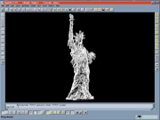
Copy CAD image of Statue of Liberty statuette. Data for this file - merged together in Copy CAD - was generated by multiple scanning systems including Picza and Ideas in 3D's proprietary system for edge data.
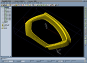
PowerMILL toolpath image of the arm of a highly stylized chair. Data for this file - initially merged together in CopyCAD - was generated by multiple scanning systems including Picza and Ideas in 3D's proprietary system for edge as opposed to surfaces data. Delcam's PowerSHAPE was used for geometry clean up prior to toolpath programming with Delcam's PowerMILL.
"No one looks at the edges when they think about digitizing, they just look at the surfaces," says Reynald Chaput of Ideas in 3D. "They seem to think that if they get the surfaces, the part's edges are somehow either automatic or irrelevant." Like all really creative people, Chaput zeroed in on what others blithely disregarded. In reverse engineering (RE), that was edges.
His solution was to perfect a highly accurate system to capture edge data, and then find a way to merge the edge data with the "clouds of points" created when surfaces are digitized. "Edges and surfaces are like a pair of shoes," he adds. "One is not much good without the other." About 80 percent of the work in his Torrance, CA shop is for moldmakers.


There's good reason for the kind of surfaces-are-all-you-need thinking that frustrates Chaput. RE evolved to meet the needs of moldmakers and tooling people to reproduce complicated curved or "sculptured" surfaces. If an object has only flat surfaces and straight edges, there's no reason to digitize it. It can easily be measured and redrawn in CAD.
There is a fundamental problem with all scanning - the amount of unnecessary data that ends up in a point cloud. "A flat surface and a curved line are defined with only three points," Chaput points out, "but scanners and digitizers pick up thousands."
Consider a 10-inch square flat surface - 100 square inches. In theory, only three points are needed. Set the scanner at 0.250 inch and it will generate 16 points per square inch. Raise the resolution to 0.025 inch and it picks up 160 points or 16,000 total for the surface. Take the resolution to 0.0025 and the point count jumps to 1,600 per inch and 160,000 for the entire surface.
To Chaput, this is insane. "Think about it," he notes. "It takes only three points to define any curve, radius, diameter or flat surface, no matter how big they are."
The smaller the resolution, or grid, the greater the accuracy, the bigger the file and the harder it is to manipulate that file. "Gridding is not good for free-form shapes," he notes. "If the scanning resolution is high enough to get the edges right - about 0.005 inch - even the fastest and most powerful PCs start to choke when you try to manipulate the file," he points out. "Bend the surface in one or two directions and the point count multiplies. If the surface is sculptured, multiplication kicks in with a vengeance."
Chaput saw that two systems were needed - one for surfaces and one for edges. Unable to find an edge-oriented scanner, he designed and built his own. Called READ (Reverse Engineering and Digitizing), it has a manual probe with a laser that constantly recalibrates the probe's location. "It's not a CMM and does not generate point clouds, just edges," Chaput explains. "It's really a 3-D electronic drafting machine. It's a five-axis machine, so it can do 'roller coaster' parting lines in molds." Accuracy is one micron and to avoid any distortion from tapping on the keyboard, READ accepts voice commands.
Chaput has three other scanner-digitizers in his 1,500-square-foot facility.
- A CNC retrofit Z-only probe on a Milltronic Partner 1 milling machine.
- A Microscribe arm.
- A Renishaw Cyclone.
Many jobs require all three plus READ.
For mold work, of course, the parting line and shut-off surfaces are critical. "If they are not done right at the beginning, the job will not come out right," Chaput observes. "The parting line establishes the parameters of the mold's core and cavity surfaces and how they will mate. The parting line also determines the quality of the molded piece in terms of tolerance and flash.
"Nothing in the real world has absolute accuracy, not even razor blades," Chaput continues. "This is what makes RE so challenging. If you look at an edge under a good magnifier, you'll see how ragged they actually are," he says. "In other words, accuracy in the real world is relative.
"Computers, however, demand complete accuracy - in that sense they are absolute. This is because in CAD the drawn - or scanned - lines and surfaces have to tie up exactly with all adjacent surfaces. They must have a snap-to fit - precise and crisp. Volumes have to be closed exactly and all surfaces and lines trimmed exactly. CAD systems do this automatically."
The other part of his solution is CopyCAD from Delcam International, Inc. (Windsor, Ontario). "CopyCAD is the only product that I have seen that can manipulate a cloud of points and really merge multiple point-cloud files into a single model," says Chaput. Thanks to the software's power, he can use up to four digitizing systems to create machineable CAD geometry.
CopyCAD does more for Ideas in 3D than just merge edge and surface files. It can convert digitized points into triangles such as those created by STL (stereolithography tessellation language) systems. STL files are cut with most any CNC machine tool.
"What's ironic is that RE files were always tessellated and always could have been machined except for one fact," said Chaput. "Even though most CAM systems have always tessellated files into triangles for machining, except for Delcam's PowerMILL and a few other innovators, they could not import those same triangles."
The scanned-in STL-type triangles can, however, make a hash of parting lines with "roller coaster" parting lines common to sculptured surfaces. Chaput avoids the problem by using PowerMILL to create a mask just above the tips of any of READ's protruding triangles. The mask's offset is usually 0.020 or 0.010 inch, depending on the scanning resolution. With the mask, a smooth parting line is generated, ensuring that the mold's core and cavity will close tightly.
To complete the process, the parting line is extruded in CAD as a NURBS (non-uniform rational B-spline surface) surface. Then the mold's shut-off surfaces are correctly attached to the parting line.
Chaput has spent his working life in RE at General Motors, the Franklin Mint and Mattel Corp. For the last 13 years he has run Ideas in 3D. He is a patternmaker by training but also has run injection molding machines, so he understands how molding and the complexities of the RE business fit together.
His customers are moldmakers frustrated by the items their customers want them to produce, such as cell phone cases, little statues, decorative bottles, carmaker ornaments and even decorative corners for pool tables. "What mold shops can't or won't do, I do," he points out. "I've dedicated my life to making reverse engineering work in the real world. Without CopyCAD and PowerMILL, I would not be in business. And this is all I do for a living."
The approach to each reverse engineering job must be fresh and original - there is no Reverse Engineering For Dummies book. "Each part has its own unique and individual character," Chaput says. "You have to treat it differently from all of the other jobs you've ever done. You fail and learn, fail and learn. That's what they call the learning curve. I have chosen pain for a living and with CopyCAD, I enjoy every minute of it."


Related Content

How to Use Automation to Minimize Mistakes and Speed Mold Build Process
A guide to capturing and reusing company knowledge and experience with software automation.
Read More
How to Machine Micron-Level Precision Molds in One Try
On-machine measurement intelligence and modification technology helps mold builders overcome machining variables and quickly produce micron-level tolerances.
Read More
Mold Builder Meets Increased Domestic Demand With Automated Cells
Burteck LLC experienced significant demand increases due to reshoring and invested in automated machining cells to step up its production output quickly and avoid losing business.
Read More
Developments in High-Speed Machining Technology
There have been many exciting developments in high-speed machining relative to machining centers and controls, tooling and CAD/CAM systems.
Read MoreRead Next

Choosing CAD Software For 3D Mold Design
The world of CAD offers many alternatives to shops that want to use the latest 3-D technology for their mold design. This article looks at the benefits of the various approaches and offers some tips on choosing the most appropriate one.
Read More
Are You a Moldmaker Considering 3D Printing? Consider the 3D Printing Workshop at NPE2024
Presentations will cover 3D printing for mold tooling, material innovation, product development, bridge production and full-scale, high-volume additive manufacturing.
Read More
How to Use Strategic Planning Tools, Data to Manage the Human Side of Business
Q&A with Marion Wells, MMT EAB member and founder of Human Asset Management.
Read More