
Limiting Stress Limits Chances of Plastic Part Failure
Molders can reduce excessive stress in plastic parts with a deeper understanding of part design, mold design and material selection.
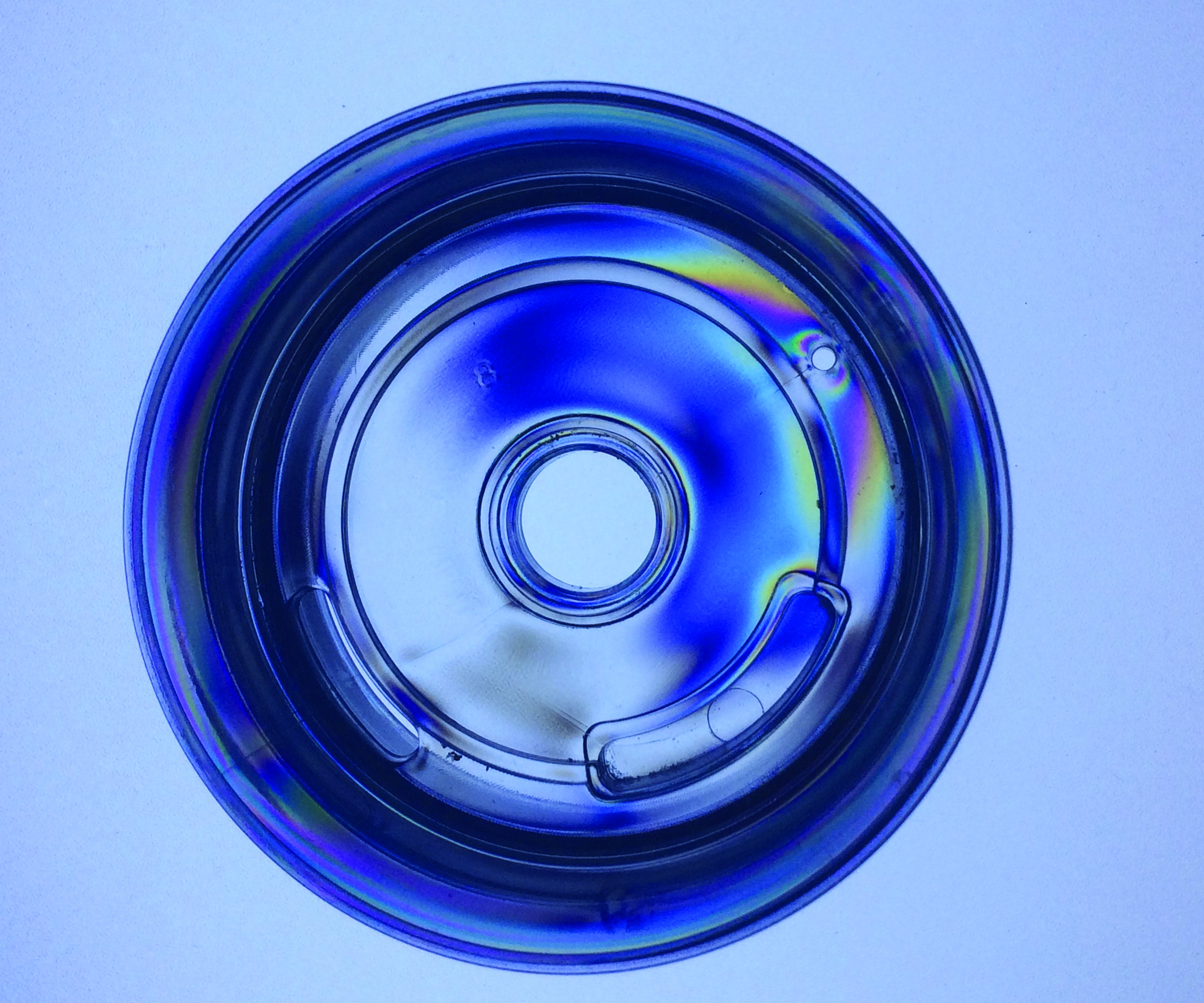
Image 1. This thermos lid molded from polycarbonate is exhibiting stress. Images courtesy of RJG Inc.
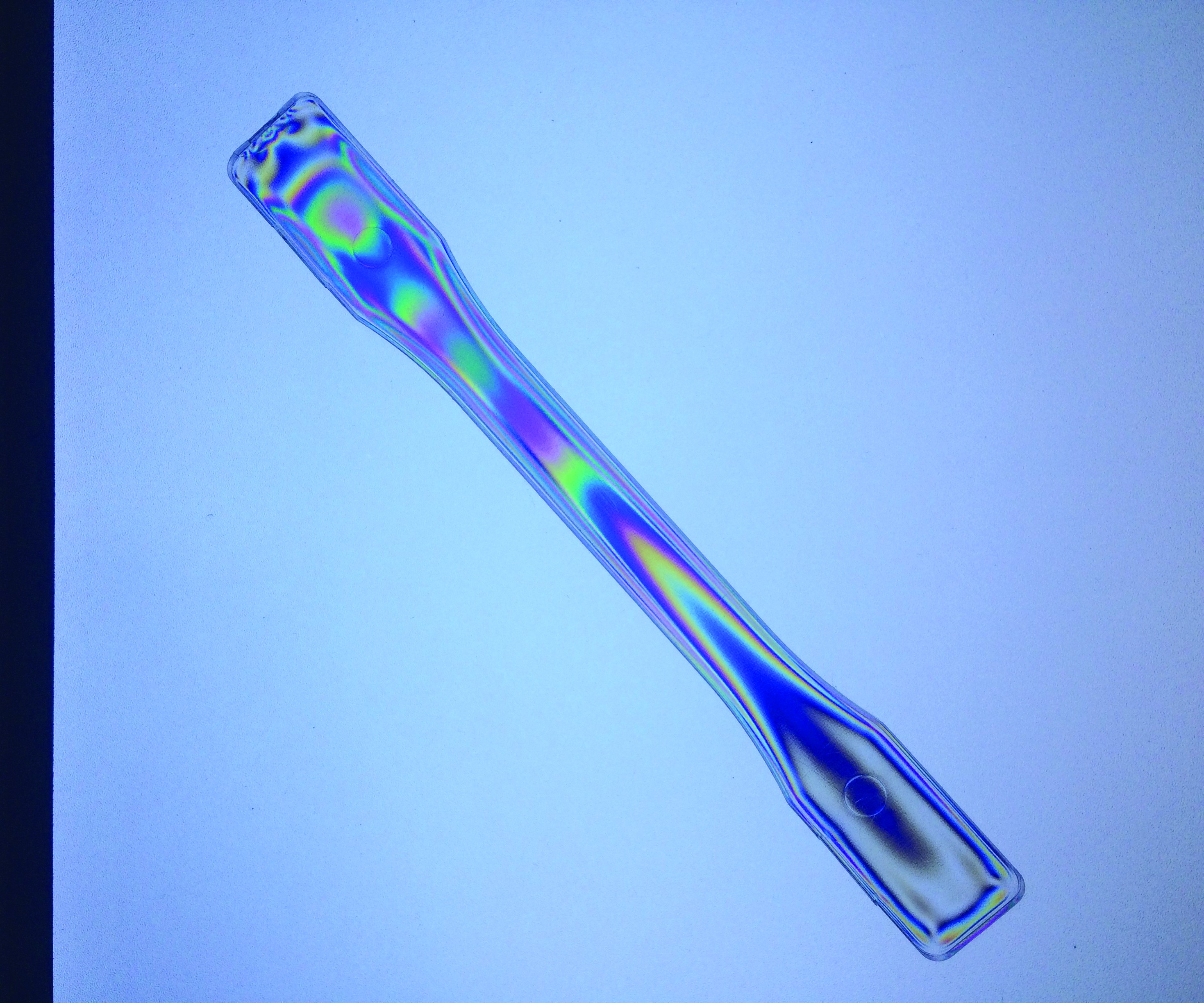
Figure 1. This ASTM tensile test bar is used to determine material properties. Images courtesy of RJG Inc.
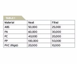
Table 1. Material selection impacts stress, and each type of material has a
recommended shear rate limit. Images courtesy of RJG Inc.
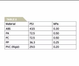
Table 2. This chart shows the rates of PSI and MPa for different types of material that experience excessive shear heating and shear stress. Images courtesy of RJG Inc.
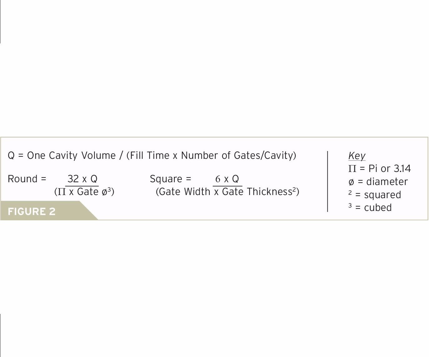
Figure 2. Use these equations to calculate the requirements necessary to avoid shear degradation and stress at the gate for a specific resin and geometry. Images courtesy of RJG Inc.
Share
Read Next


We all work long hours and try to meet unreasonable expectations set by someone who has no idea what is required to get the job done. However, we’re not the only ones who feel this stress. Plastic also feels stress when it is handled inappropriately. If neither situation is managed properly, the engineer and the plastic part (see Figure 1) will certainly be stressed out.
Stress is the load (force) per unit area that tends to deform the body on which it acts. Stress is inherent to injection molding because of flow rates, pressures and temperatures applied to the material during processing. However, excessive stress in a molded part can cause issues with paint or chrome adhesion to the surface. In-molded stress can cause premature functional failures as well, especially if a part must pass chemical testing, physical loading or thermal cycling.


A basic understanding of plastic is necessary before tackling stress. Close your eyes and visualize it’s mid-August at the amusement park, and you’re on vacation with your family. It’s a scorching 98°F, and you are standing in line for the seventh ride on the Tilt-A-Whirl. You notice a loose group of people congregating around the main entrance to the line, smiling and conversing with one another. As they inch closer to the single file line, there is less talking, the temperature rises and several individuals start getting feisty because of the lack of space between them.
Plastic goes through a similar experience when changing thickness, switching directions or squeezing around sharp corners, and these are just a few of the factors that influence overall stress.
Part Design
The design of a part has a large impact on the overall stress of the plastic. Here are three ways you can decrease stress on your parts through design:
Keep wall thickness consistent. This isn’t easy given today’s complex geometries because as thickness changes occur, orientation, compression and cooling stresses vary dramatically. Orientation stress is the alignment and stretching of the molecular chain during the filling phase. It’s like a rubber band. If a polymer chain is stretched too far or too fast, it can break. Compressive stress occurs during the packing phase when material is added to the cavity to compensate for shrinkage. Cooling stresses happen when the material contacts the cavity wall and the material tries to shrink back to its unoriented, relaxed state. Again, it’s like a rubber band. If the molecular chains are stretched and held under constant load, they will eventually break.
Eliminate sharp corners. The polymer is already under stress from filling, packing and cooling during the process. A sharp corner is another area where the material may not receive proper treatment. It’s highly likely that sharp corners will add stress to plastic, which leads to functionally weak parts. This is because when load is applied, sharp corners become the weakest link in the chain, causing parts to fail in this region. Basically, sharp metal edges in molds will cut a polymer chain as it passes much like a sharp knife cuts skin. Edges with radiuses will not cut the polymer as it flows, in the same way a dull butter knife is unlikely to cut skin.
Also, sharp corners can generate shear imbalance within the part’s geometry, which further increases the potential for stress. Shear is caused by the injection rate as the polymer chains flow past one another during the filling phase. Shear imbalance is caused by the material changing directions in the runner system or within the part geometry, especially around sharp corners. The more times a material changes direction, the more shear is put into the material. Higher shear rates will increase the temperature of the molten material flowing through the mold. If the shearing is high enough, the temperatures could exceed recommended limits, causing the polymer chain, the additive or both to break. Once this breakage occurs, the part becomes weaker and likely fails functional testing.
Design core-out features correctly. Core-outs are features like through holes, blind holes or any element around which the material must flow. Visualize a rock in a river. The water must flow around that rock and reconnect on the other side. In molding terms, the rock is the core-out, the river shape is the part geometry and the water is the flowing plastic. Core-outs can come in all shapes, sizes and locations within the mold cavity.
As material flows around the core-out and tries to shrink during the cooling phases, the metal that forms these holes prevents the material from returning to its natural, relaxed state. When the material is oriented and stretched during filling, it is no longer in a straight line. It must bend to the shape of the core-out. When the material cools, it tends to relax, but the metal core-out in the mold will not allow that to occur. The polymer chain is stuck in a stretched-out, bent shape.
Remember that every time the material flows around a feature, there is an increased chance of stress. Keep in mind also that mold designers and molders cannot overcome what is inherent to a specific geometry. To correctly design core-out features, avoid corners or edges, and place gating in a proper location. This way, the material can flow in a parallel direction, not a perpendicular direction, to the feature.
Material Selection
Another variable that design engineers can control to impact stress is material selection. Each material has a recommended shear rate limit (see Table 1), and if that recommendation is violated, excessive shear heating and potential shear stress will result (see Table 2).
A consistent flow rate through the water channels is critical for an even part temperature at ejection.
The shear rate limits of the polymer are not the only concern. Consider also the shear rates of the various additives (color, ultraviolet (UV) stabilizer, heat stabilizers and lubricants) that are compounded to make the polymer. And, since most additives do not come with processing recommendations, it’s difficult to understand the limitations. This can result in additive degradation before the polymer chains are broken. Once that occurs, the molded part’s expected performance is compromised, leading to a potential performance failure.
All injection molding thermoplastic materials shrink when they cool. As this occurs, the polymer chains try to return to their relaxed state. The combination of orientation, compression and cooling prevent the polymer chains from returning fully to that state.
Mold Design
Mold design, specifically gates and cooling channels, is another factor that has a huge impact on stress within a molded part. Gate size, location and quantity for a mold must be properly designed or the shear heating and stress on the material can exceed recommended ranges quickly. In other words, dimensions, tolerances, performance criteria, material limitations (temperature, shear stress, shear rate) and processing parameters (flow rates, pressures, cooling) of a mold require consideration. Otherwise, that material will be compromised, which breaks the molecular chain and leads to part failure.
Use the equations in Figure 2 to calculate the requirements necessary to avoid shear degradation and stress at the gate for a specific resin and geometry. Each material has shear rate and shear stress limits. The equation focuses on shear rate. With known parameters, such as part weight, an engineer can select fill times, size and number of gates to design a gate that will not exceed the material manufacturer’s recommendations. The equation also gives the molder a process window. For the molder to make fill-time adjustments for cosmetic or machine performance requirements, the mold designer must select the proper size and number of gates.
Inappropriate gate size can compromise effective pressure transfer from the molding machine to the end-of-fill in the cavity. This includes undersized gating. Incompatible gate size causes problems like voids, sink, warp, dimensional inconsistency or short shots in molded parts.
Cooling channel placement also dramatically affects the ability to remove heat from the plastic part. If heat is not removed evenly across the part, then the shrink rate will be drastically different. This yields a product with varying amounts of stress and a high likelihood of warpage.
It is possible to manage a small portion of inherent stress through processing. The first step is to ensure that the resin’s actual melt temperature is within the recommended range from the material manufacturer. To verify the melt temperature, complete an air shot with normal machine parameters, and insert an immersion probe into the center of the melt puddle. If the temperatures are run below the suggested range, then injection pressure will be higher, inducing additional, unwanted stress.
Then, ensure that the proper flow rate is set for the injection phase. A shear rate that is set too high at the gate can be higher than the material’s limitations, which can cause the melt temperature to increase dramatically and can degrade the polymer or the additives. Here, it is important to understand that the polymer chains are oriented and stretched out during the filling phase, which means that simply changing the flow rate will vary the amount of stress and cause warpage, sinks, voids, short shots, assembly issues and part performance problems.
The amount of pack pressure and time is another relevant factor. After the filling phase, the process transitions into packing, where the molecules are now compressed with pressure applied from the injection unit. Often, these variables are set based on part weight or dimensions. Nonetheless, do not ignore the possibility of overpacking, which typically occurs near the gate area in response to overcoming an enormous pressure gradient across the cavity.
Lastly, consider mold cooling and its impact on stress. The molder only controls coolant temperature, flow rate and time. When the mold temperatures are set lower than recommended, there could be excessive stress locked into the molded part. Hot material flowing over a colder mold surface (even when set correctly) can lock stress into the polymer chain. For example, a mold temperature of 180ºF and a melt temperature near 550ºF yields a certain amount of stress. However, if the molder set the temperature controller to run at 80ºF to mold parts faster, the thermal shock will be higher and the locked-in stress will be greater.
A consistent flow rate through the water channels is critical for an even part temperature at ejection. If the temperature range across the part is wide enough, significant shrinkage will occur after molding. This can vary drastically across material and geometry. Generally, when the temperatures vary more than 20ºF across the part, it is time to address the cooling line design. Set the cooling timer on the press to ensure that the part is rigid enough for ejection. There is no general guideline for the timer, which is dependent upon cavity geometry, part thickness, polymer type, mold steel type, cooling channel placement, cooling medium or temperature used and process parameters (melt temperature, flow rate, pack/hold time and pack/hold pressure). In some cases, when the timer is set too high, the part will cool dramatically, making ejection difficult. White stress marks around ejector pins are an indication that the part is not releasing from the mold surface well.
If a part has struggled with post-mold warp, passing optical requirements on a lens, chrome adhesion, environmental protocols or drop testing, then it could have too much stress locked into the molded component. Determining whether that stress is related to part geometry, material, mold or process is crucial to solving this common quality issue. It takes collaboration to minimize that stress on the molded part as well as the people involved.
About the Contributor
Jeremy Williams
Jeremy Williams is a consultant/trainer for RJG, Inc.’s TZERO consulting service. He has more than 17 years of experience in the plastics industry serving the medical, automotive, furniture and appliance industries. He earned his Master Molder II certificate in 2011, became a Train the Trainer in 2012 and started at RJG in 2015.


Related Content

Standard Hot Runner Cable Range Extension
Hasco is now offering its H12251 cable in two different lengths and four different wiring standards.
Read More
The Ins and Outs of Hot Runner Temperature Control
A training checklist that explains the why and how of proper hot runner temperature control and system management.
Read More
Hot Runner Systems, Controllers, Auxiliary Injection Unit Exhibitions
Mold-Masters exhibits a wide variety of new and enhanced systems and technologies at K Show like the TempMaster manifold plastic leak detection, the PET-Series two-stage hot runner system and Fusion Series G3.
Read MoreRead Next

Are You a Moldmaker Considering 3D Printing? Consider the 3D Printing Workshop at NPE2024
Presentations will cover 3D printing for mold tooling, material innovation, product development, bridge production and full-scale, high-volume additive manufacturing.
Read More
How to Use Continuing Education to Remain Competitive in Moldmaking
Continued training helps moldmakers make tooling decisions and properly use the latest cutting tool to efficiently machine high-quality molds.
Read More
How to Use Strategic Planning Tools, Data to Manage the Human Side of Business
Q&A with Marion Wells, MMT EAB member and founder of Human Asset Management.
Read More