

Molds continue to shrink in size, forcing cutting tool manufacturers to develop techniques and tool geometries for the smallest cuts and biggest productivity boosts.
Images courtesy of Seco Tools.

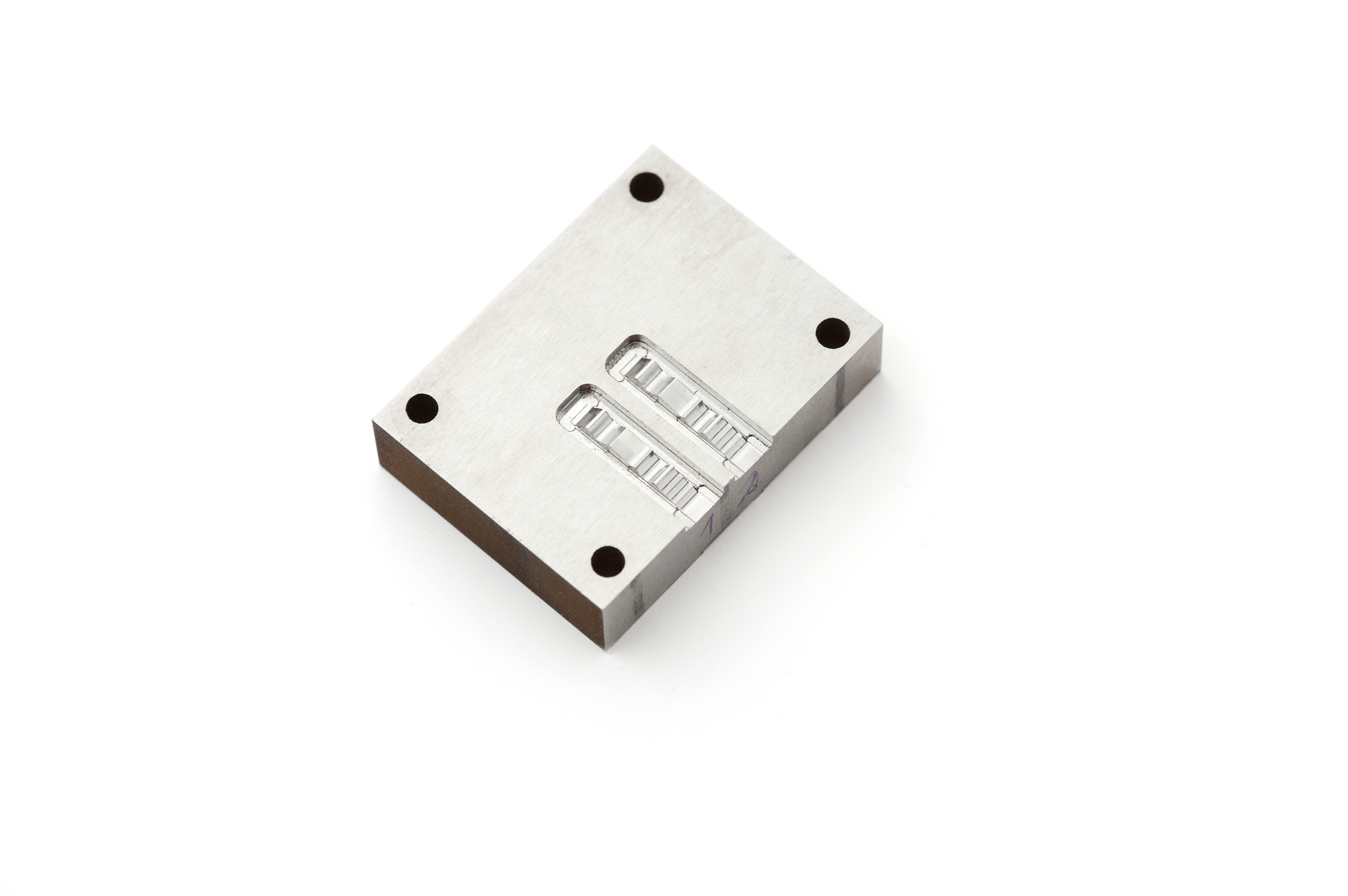
The challenges for mold manufacturers get bigger as part features get smaller, especially when the cutting tools are a tenth of a millimeter in diameter and are required to machine molds and dies made from tough materials.
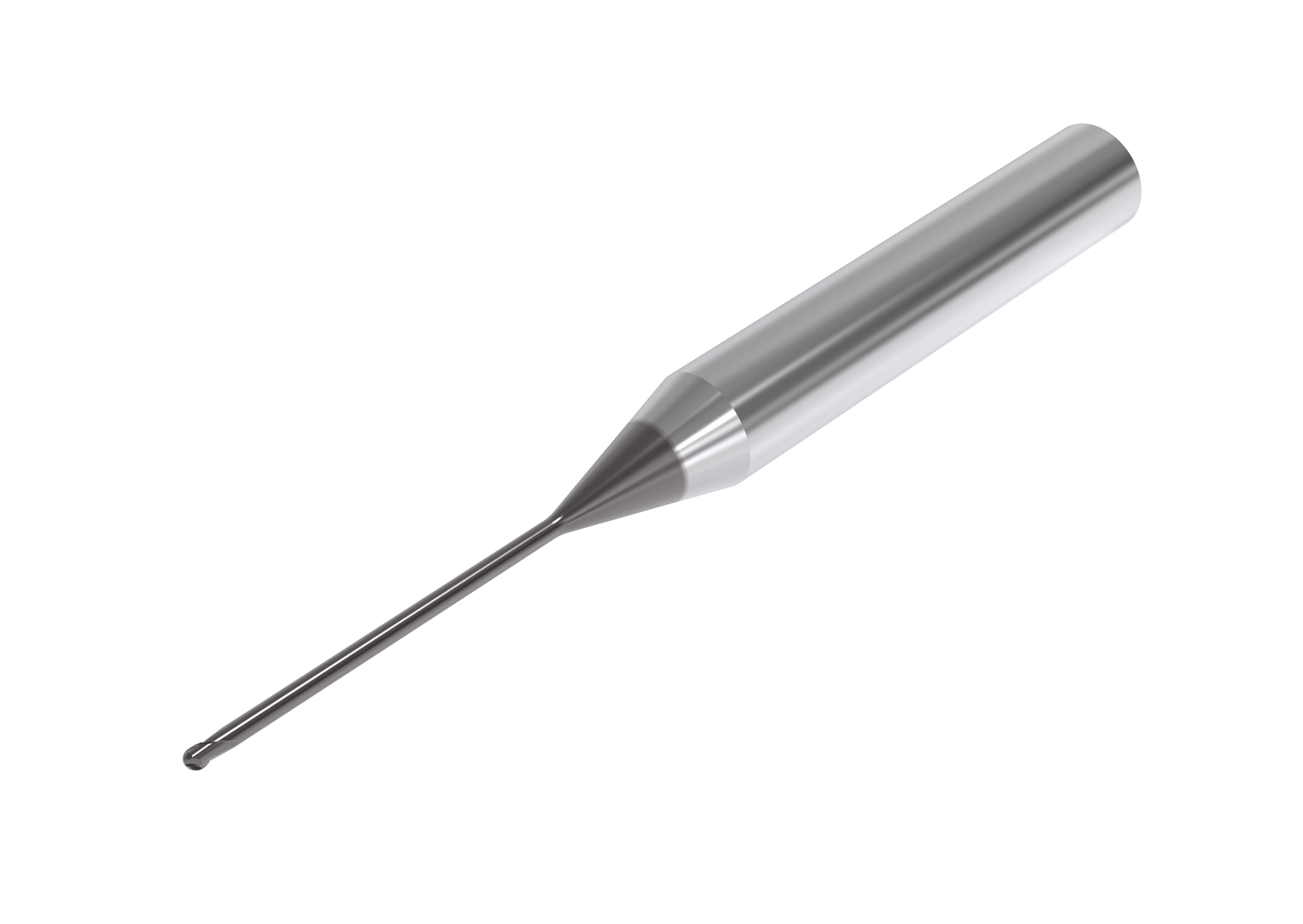
The continual micro trend is pushing cutting tool manufacturers to develop advanced tool tip geometries.
Ball nose end mills with advanced tool tip geometries ensure the free-cutting properties necessary for chip consistency and long tool life.


Moldmaking is a lot about miniaturization. Whether it’s components for lifesaving medical devices or the scored grip on the bottom of a tube of lip balm, manufacturers use molds to generate tiny part features. As these molds continue to shrink in size, cutting tool manufacturers continue to provide techniques and tool geometries for the smallest cuts and biggest productivity boosts.
As part features get smaller, the challenges for mold manufacturers get bigger, especially when the cutting tools are a tenth of a millimeter in diameter and are required to machine molds and dies made from tough materials, such as steels and alloys ranging from 48 Rc (S7, 420 stainless and H13) to 60 Rc and above (A2, D2, and high-speed steels). This trend continually pushes cutting tool manufacturers to develop advanced tool tip geometries, especially for ball nose end mills, to ensure the free-cutting properties necessary for chip consistency and long tool life.


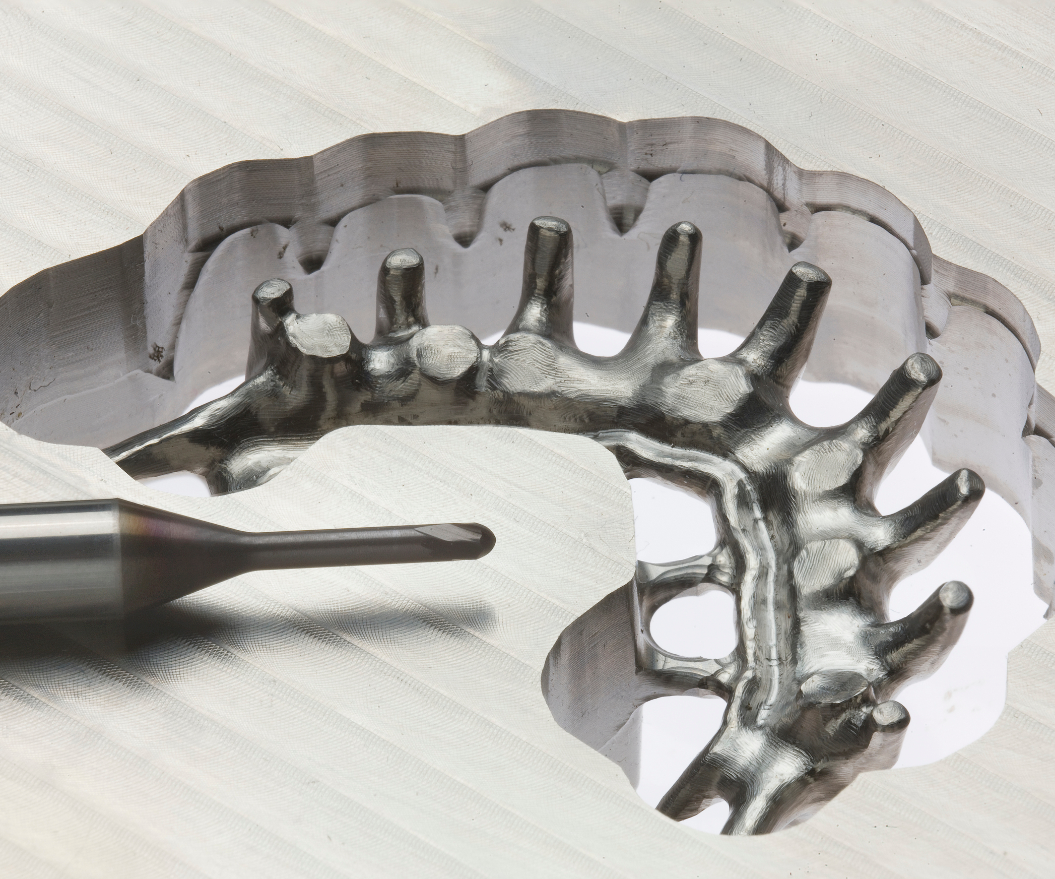
Tool geometry is never simple at such a micro scale. Even the sharpest edge on a typical cutting tool will have nicks and imperfections caused by the grain of the grinding wheel used to produce it. Using that same size grit on a micro-diameter tool would make it virtually impossible to keep the edge sharp. In fact, on the smallest-diameter tools, the grain size of the typical grinding wheel will be just as large as the tool’s edge.
Good chip formation requires a balance between speeds and feeds, but this can be deceptive at the micro level.
Big Considerations for Small Tools
Today’s advanced grinding software and machines make it possible to smooth out cutting edges and create free-cutting tips for micro tools. Micro tool geometries typically involve newer S-shaped tips that are freer cutting by design rather than traditional chisel-point geometries of other cutting tools. Also, physical size constraints mean that four flutes are the maximum, with two flutes being more common. This is because, with most machine tools, end mills at sizes below 1.0 mm in diameter can barely reach the maximum feed rates necessary for two flutes, much less four.
Once you have the optimal micro milling tool tip geometry that allows for freer cutting in hardened steel along with good cutting-edge strength, it’s time to consider the ability to hold and maintain an edge for consistent tool life. Remember a dull tool or an end mill with suboptimal geometry will just push material around instead of cutting it. Even the tiniest flaw may be the difference between a perfect cut and a scrapped part when working at the micro level. To combat this challenge, some cutting tool manufacturers make solid end mills with a cobalt blend around 8 to 9 percent to provide a good balance between wear resistance and hardness.
Tool runout is another key micromilling consideration whose prevention requires more than optimal tool tip geometry. When cutting small part features, a little runout can quickly cause big problems, such as reducing tool life by 50 percent. Unlike long tool overhang strategies or heavy roughing applications, micromilling typically involves shallow depths of cut and small radial engagement, so it generates minuscule levels of vibration because the chips are not big enough. The real culprit is a lack of machine movement smoothness often due to a machine not having a long enough lookahead control capability or poor programming strategies that fail to maintain constant chip load. The result is jerky machine movements that can cause instant tool breakage.
However, even if the process is stable (proper cutting tool, proper speeds and feeds, rigid setup and a truly capable machine tool), tool life may still be suboptimal. One solution is to use advanced silicon coatings on solid end mills to increase cutter life by up to 50 percent by boosting a tool’s heat and abrasive resistance. Dirty collet bores, ambient temperature changes or unstable machine foundations are other conditions impacting the micromilling process.
Chip load consistency, or having a machine tool maintain a consistent feed rate, is another important aspect of the micromilling process because of its average chip thickness at tenths of a thousandth of an inch.
Tool runout is another key micromilling consideration whose prevention requires more than optimal tool tip geometry.
Good chip formation requires a balance between speeds and feeds, but this can be deceptive at the micro level. Unfortunately, many manufacturers approach micromachining with a high-rpm spindle speed cutting strategy, which can negatively impact chip formation. The reason is that it is practically impossible to run at those feed rates and maintain a consistent chip load; instead, the tool is pushing material instead of cutting it. Even the fastest machines (feed rate) fail to accelerate or decelerate quickly enough to keep up with spindle speeds. The results are poorly formed chips, a subpar surface finish and sharply diminished tool life.
The solution is to speed up and slow down. It may sound like an oxymoron, but after a programmer figures out the average functional feed rate by trial and error, he or she can adjust the spindle speed to the appropriate rpm. This is because parameters for consistent chip load are different from one tool to another, as well as from one part to another. What many shops will do, however, is keep a log or create a database of the part, tool and parameters that have been successful.
For example, a cutting program set to 40,000 rpm at 50 ipm is well within the range of advanced machine tools, but because of the short micromilling cutting paths, it simply can’t feed that fast. Instead, the actual average speed is 25 ipm, and a reduction in spindle speed to 20,000 rpm reestablishes equilibrium and a constant chip load.
Trial and error is an option for developing these processes, but cutting tool manufacturers familiar with the wide range of materials and cutting tools used today can also help with these calculations.
About the Author
Jay Ball
Jay Ball is a product manager, solid carbide end mills at Seco Tools.


Related Content

The Benefits of Hand Scraping
Accuracy and flatness are two benefits of hand scraping that help improve machine loop stiffness, workpiece surface finish and component geometry.
Read More
Moldmakers Deserve a Total Production Solution
Stability, spindle speed and software are essential consideration for your moldmaking machine tool.
Read More
6 Ways to Optimize High-Feed Milling
High-feed milling can significantly outweigh potential reliability challenges. Consider these six strategies in order to make high-feed milling successful for your business.
Read More
Treatment and Disposal of Used Metalworking Fluids
With greater emphasis on fluid longevity and fluid recycling, it is important to remember that water-based metalworking fluids are “consumable” and have a finite life.
Read MoreRead Next

How to Use Continuing Education to Remain Competitive in Moldmaking
Continued training helps moldmakers make tooling decisions and properly use the latest cutting tool to efficiently machine high-quality molds.
Read More
Are You a Moldmaker Considering 3D Printing? Consider the 3D Printing Workshop at NPE2024
Presentations will cover 3D printing for mold tooling, material innovation, product development, bridge production and full-scale, high-volume additive manufacturing.
Read More
Reasons to Use Fiber Lasers for Mold Cleaning
Fiber lasers offer a simplicity, speed, control and portability, minimizing mold cleaning risks.
Read More