
CT Scanning Helps Micro Molder Reduce Cost of First Article Inspections
CT scanning services performed by 3D ProScan, a division of NyproMold Inc. provides MTD Micro Molding with accurate, high-resolution internal and external measurements performed about seven times faster and at significant cost savings.


MTD Micro Molding (MTD) is based out of Charlton, Massachusetts. The company is all about custom-designing and building very small molds for molding microscopic plastic parts for medical devices, including implantable components that are predominantly bioabsorbable. That is all they do. Given the nature of its work and the industry that it serves, the company must meet strict customer specifications for every part that it produces. First article inspections (FAI) are always required, using very high-end, dimensional inspection equipment and measurement processes. The challenges of completing a first article inspection are magnified when the parts are extremely small. For example, MTD has been known to produce 520 parts from a single pellet of plastic. According to John Clark, project manager, there can be a high level of uncertainty and variation in the measurements when segmenting parts this small. This is because optical measurement systems are only repeatable on crisp edges. However, anytime a mold builder segments a micro-sized part, he or she smears the edges. “For example, when cross-sectioning three parts for an FAI, it can be expected that all three measurements will be slightly different based on the skill level of the person that is segmenting the parts and on the quality of the cutting tool that the person uses to segment the part,” he says.
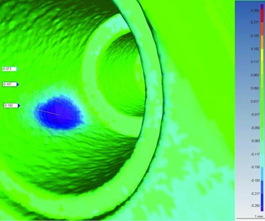
This is what a part-to-CAD overlay would look like. 3D ProScan uploads the .STP file of the part and then lays the scan data over it. The rainbow-like scale on the right-hand side indicates how far away one is, in a positive and negative direction, from nominal tolerance requirements. Here, the blemish is an area with sink. The darker blue or purple the color, the deeper the hole. Reds indicate excess material or flash. Warp is another issue that can be highlighted using CT scanning technology. Image courtesy of 3D ProScan.
Take a recent project in which MTD designed and built a mold for a part that had more than 120 drawing dimensions. “The sheer number of dimensions involved in this project created a need for us to use computed tomography (CT) scanning, if we were going to be cost-effective and avoid inflated lead times for our customer,” Clark says. MTD enlisted the services of a division of NyproMold Inc. called 3D ProScan, a product validation and metrology lab. NyproMold Inc. houses 3D ProScan within its headquarters in Clinton, Massachusetts. 3D ProScan was established in 2012 to provide industrial tomography solutions for plastic injection molding, medical device, packaging and personal healthcare products that it manufactures internally and that external customers like MTD manufacture. 3D ProScan performs these services on its Zeiss Metrotom 800 industrial CT system.


Before CT scanning became an acceptable measurement solution, completing FAI measurements for a design with 120-plus dimensions using standard metrology equipment like MTD’s OGP vision system required “cross-sectioning.” This literally meant taking a cutting tool and slicing or sectioning a part to reveal an internal feature. This process also required that each drawing view had its own separate fixture to hold the part in the correct orientation so that the dimension(s) could be accurately captured in that view. Part dimensions that are challenging to capture with traditional measurement methods include complex datum alignments, multiple cross-section callouts, draft angles, hidden features like thin internal walls, small radii and multiple concentric, perpendicular and flatness callouts. “The measurements are only as good as the fixtures used to hold the parts,” he says, explaining that since an FAI includes all drawing dimensions, not just those deemed critical to function, most come from a measurement system that is based on manual capture.
Additionally, the total measurement time for just one, single view could take several hours depending on how intricate a fixture must be to facilitate the capture of the section view dimensions, plus the setup time. “Attempting to undertake these challenging measurements without CT scanning raises the possibility of uncertain and inconsistent measurements which potentially could cause project delays,” Clark says.
More Accurate Measurements, Reduced Lead Times
Clark says that with CT scanning, no segmenting is required, which provides a truer dimensional measurement. “In my experience, CT scanning always offers a better solution for a standalone, molded component,” he says. It is particularly true when measuring internal part features because most internal features cannot be seen from outside the part. There really is no accurate way to measure internal features that require sectioning without CT scanning.
CT scanning also provides accurate measurements with high resolution, which is extremely important in micro designs with tight tolerances. Clark says MTD commonly sees tolerances down at the micron level, beginning at ±0.010 millimeters (0.0004 inch) and up from that point.
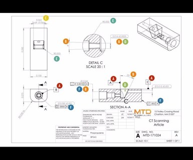
This drawing, provided by MTD Micro Molding, illustrates complex features that can be captured accurately with the use of 3D ProScan's CT Scanning services.
Part-to-CAD overlays, which are visual representations of the 3D point cloud of the scanned part compared to the 3D CAD model of the part, are another invaluable tool for MTD because they help illustrate material shrinkage issues, part warpage and so on. Melissa Butrie, business development manager at 3D ProScan, explains that after the 3D scan and CAD model are aligned and overlaid using the software, tolerances are applied. “There is a color-coded chart based on measured variation. If something is out of tolerance in a positive direction, the area will appear dark red, indicating warp or excess material. If something is out of tolerance in a negative direction, it will appear dark blue, indicating shrinkage,” she says.
CT scanning also reduces the time to collect the required data from 17 or 18 days to about two days. “We were able to scan four parts at one time, so we had our metrology department quote a four-part FAI for comparison. CT scanning proved to be seven times faster than cross-sectioning,” Butrie says.
Additionally, it is critical for the MTD team to receive timely, detailed and accurate reports with corresponding bubble prints. Butrie explains that when 3D ProScan completes an FAI, the customer receives the overlays and a spreadsheet or report that lists the nominal and measured dimensions. 3D ProScan indicates if they are out of tolerance. The customer also receives the bubble or ballooned print. “The bubble print is the customer-provided drawing with circled numbers that we place at the dimensions so that the customer can easily identify them on the report. So, if dimension 47 is indicated as unacceptable on the report, the customer can look at the bubble drawing and quickly identify where that dimension is on the part,” Butrie says.
More Cost-Reducing Advantages
Butrie says that the time savings that CT scanning technology enables over cross-sectioning contributes to considerable savings for MTD, and she estimates those savings to be about 63 percent. Clark says the timing is accurate in that MTD can generate measurements seven times faster with CT scanning over other methods. However, “given MTD’s operating costs, the actual cost savings in most cases are 80–85 percent more than if we were to do cross-sectioning and measurements in-house.”
Eliminating the need to build custom fixtures to capture the 120 dimensions also helped MTD significantly reduce costs. Again, a fixture design is dependent on the part that is being sectioned. Clark says that the custom fixture for a part with simple geometry can cost up to $4,000 and take a week to manufacture and qualify. A custom fixture for a part that is very rich in features requires a more elaborate design to ensure the preservation and protection of the features for measurement. This more complex fixturing can cost up to $7,500 and take two or three weeks to produce and qualify. In either case, one can expect to add four to six weeks to the overall project to ensure sufficient time to manufacture the custom fixture, prove it out, train personnel on its proper use, section the parts and then begin the metrology process, he says.
Clark says that there are times when the company cannot use CT scanning, such as when there is a metal component or metal mineral in the resin that is part of the finished good. “The metal dramatically diffuses the image that the CT scan produces.
“CT scanning is an invaluable tool to have available for our micromolding customers who have part designs with many drawing dimensions or dimensions that are impossible to measure or both,” Clark says. “3D ProScan has proven to be a great partner as they stand by the accuracy of their measurements, are extremely responsive and provide a cost-effective, quick-turnaround solution for MTD. Now that we have a CT scanning partner, the biggest strain on our metrology team is bagging up the parts so we can ship them to 3D ProScan to perform the FAI.”


Related Content

Evaluating Metal Powders for Conformally Cooled Mold Inserts
Mechanical properties and design software techniques reveal the benefits of a modified high thermal conductivity metal powder for 3D printing in moldmaking.
Read More
IMTS Showcases Software, Additive Manufacturing, Inspection and Measurement Tools for Moldmakers
MoldMaking Technology previews a selection of the software, additive manufacturing, inspection and measurement tools that will be present at IMTS.
Read More
What Does Surface Roughness Mean in Moldmaking?
To improve mold performance, reduce wear and produce high-quality molded parts, mold builders must understand surface texture and how to properly measure, analyze and control it.
Read More
Technology Roundup: New/Improved Technologies You Don't Want to Miss
With all the technology joining the market, moldmaking is a versatile, ever-evolving industry. As such, this technology roundup has no specific theme — it features a variety of products for applications and solutions across the industry.
Read MoreRead Next

Shrink-Fit System Helps Moldmaker Boost CNC Accuracy, Productivity and Tool Life
Fine tuning a CNC machine for maximum speed and having the ability to run lights-out machining means controlling a wide variety of elements like tool holding. The inherent benefit of shrink-fit technology, as compared to other tool holding options, is that it virtually eliminates the toolholder as a variable for error.
Read More
Reasons to Use Fiber Lasers for Mold Cleaning
Fiber lasers offer a simplicity, speed, control and portability, minimizing mold cleaning risks.
Read More
How to Use Continuing Education to Remain Competitive in Moldmaking
Continued training helps moldmakers make tooling decisions and properly use the latest cutting tool to efficiently machine high-quality molds.
Read More