
Hot Runners and Valve Gate Systems: A Moldmaking Team
Valve gates provide several advantages when using hot runners, including better appearance, safety and an overall better product. There are several types of valve gates, and it is important to choose the right one for your project.


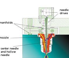
Figure 9: Core-back technology with coaxial needle valve nozzle for the production of a double-ply cup or sandwich cup.

Figure 8: Melt control in the coaxial valve gate
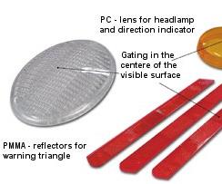
Figure 5: Valve gate applications.

Figure 10: Mold for 4-drop coaxial valve gate.
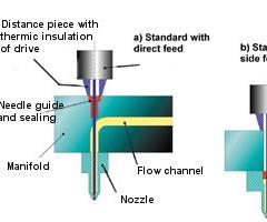
Figure 3: Standard valve gate systems.

Figure 1: Gating variations
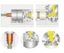
Figure 7: Standard valve gate.
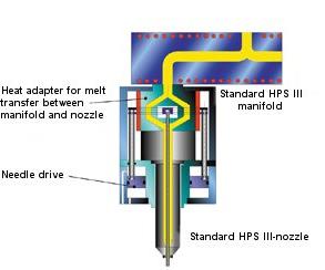
Figure 2: Compact valve gate system.
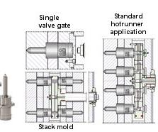
Figure 4: Variations of installation.

Figure 6: Valve gate used in large molds.

Figure 11: Coaxial valve gate as machine nozzle.
The decision to use valve gate systems can be made for different reasons. In many cases, the cosmetic aspect is of importance, meaning that the application requires gating onto a visible area of the part with a near invisible gate mark. All other gating methods result in a varying degree of vestige height.
Nevertheless, a gate area with a low vestige can also be achieved by using a conventional hot runner system. This can be done with small gate diameters or by using special techniques to force a so-called "cold vestige." The problem with conventional hot runner systems is that small changes in the processing conditions can cause a perfectly adjusted vestige to quickly run out of the permissible tolerances again. For that reason, valve gate systems are used in a growing field of applications because of their less delicate behavior regarding the changes mentioned above.


From a technical point of view, valve gate technology enables the production of low-stress injection molding parts, which almost always meet the requirements of a very low vestige. As a result, the lower degree of stress when gating with valve gate systems becomes relevant. When using a valve gate there is no need to control the vestige by trying to achieve small gate diameters. Small gate diameters of course lead to higher shear rates and therefore inevitably result in a higher degree of orientation. Areas with a high degree of orientation cause internal stress, so warping of the part is a high risk. For example, a gate diameter of 0.8 mm for a part with a shot weight of 10 g results in a local shear rate of approximately 150,000 1/s. When a valve gate with a needle diameter of 2.5 mm is used, the shear rate in the gate area is approximately 6,000 1/s.
Safety is another factor to consider when using valve gate systems. For example, valve gate systems are used to avoid stringing in fast cycling molds. Stringing always occurs when the melt in the gate has no chance to freeze properly within the time given. This can happen in fast-cycling molds as well as with large gate diameters or with an improper temperature control. With valve gate technology, stringing can be avoided in most cases. The mechanical shut-off ensures that the gate is always sealed properly, regardless of the gating diameter. However, in case of very large needle diameters, even valve gate systems can cause problems. When operating with short cycle times the needle stores so much heat during injection that a bonding effect in the needle area can occur.
Using valve gates also provides a processing improvement gained by the precise control of the shut-off time. When molding multi-point gated parts, the formation of flow lines can be avoided by a sequential opening of the needles. By using this method a controlled melt flow can be achieved so that a frontal meeting of flow fronts can either be avoided or be placed in less critical areas of the part.
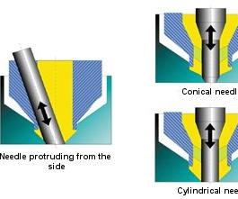
Figure 1: Gating variations
Valve Gate System Gating Variations
Two important sealing principles have been established for the processing of thermoplastics with valve gate systems (see Figure 1). One of them is the conical needle geometry. During closing the conical needle moves into corresponding gate geometry in the mold insert. When using this principle, the closing power of the needle drive must be limited to avoid damage of the mold insert. When the needle closes the melt is displaced from the narrowing gap.
In lieu of the conical needle, the cylindrical form is often used. Here the mold insert normally has a conical entrance leading into a short cylindrical bore. The melt in the cylindrical area, which measures only some tenth of a millimeter, must be pushed into the part when closing the needle. Considering the low melt volume and the shrinkage, this normally has no affect on the molded part.
Needles protruding from the side into the gate on an angle offer some advantages because the melt flow is only slightly blocked in their open position. However, because the non-symmetrical layout of this gating method causes a higher wear, this method has not gained a large market acceptance.
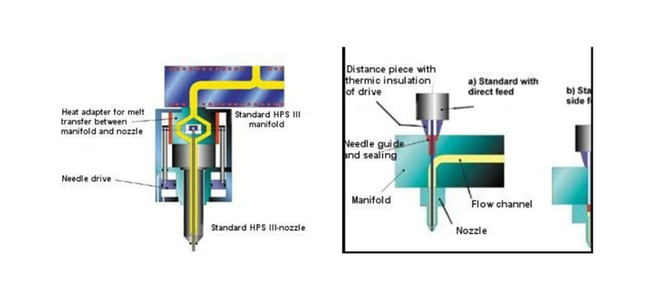
Figure 2 (left), Figure 3 (right)
Valve Gate System With Integrated Needle Drive
An in-line valve gate with an integrated needle drive is a general purpose system compared to standard designs (see Figures 2 and 3). Due to the construction of the nozzles, the valve gate can be handled like a "conventional" hot runner system. As shown in the description regarding function and mounting location, a fixed mold half consists of a normal clamping plate, a manifold frame plate including a standard manifold and a nozzle retainer plate (see Figure 4). The in-line valve gate can be used as a freestanding single tip as well. There is no need for any changes in construction. Examples for applications are shown in Figure 5.
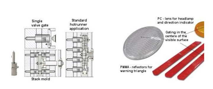
Figure 4 (left), Figure 5 (right)
When used in stack molds, the in-line valve gate offers decisive advantages. Since there is no need to place the needle drive behind the manifold and to guide the needle through the manifold, a perfectly symmetrical positioning of the cavities can be achieved. This means optimal utilization of mold and machine. Furthermore, two in-line valve gate nozzles that are positioned exactly opposite each other can be used for a central leakage-free melt-transfer in stack molds without having to use an accumulator cavity.
In large molds with deeply immersed nozzles, very long needles must be used. At the same time, the nozzles are screwed into the manifold. To ensure that the desired position of the needle is reached when the manifold is heated up and thermally expanded, the needle must be adapted while the system is cold or jamming of the needle and wear in the needle guides is possible. This problem can be eliminated by using a valve gate system with an integrated needle drive as the final stage of a long nozzle (see Figure 6). The position of the valve gate is fixed within the mold and a flexible pipe connects the valve gate to the manifold. Due to the fact that the needle is contained within the valve gate assembly, it experiences smaller growth and is not affected by other elements such as manifold growth.
Standard Valve Gate
The standard valve gate is of importance when a low system height is required. Because the needle drive is positioned in the clamping plate, the total height of the system is similar to a normal hot runner system (see Figure 7). However, when using this method the manifold of the hot runner system must be specially adjusted to the valve gate system. Either additional sealing elements or at least clearance bores for the needle must be provided. The clearance bores must be positioned so that they do not interfere with the melt channels in the manifold. An in-line valve gate nozzle with a needle drive that can be operated mechanically, hydraulically or pneumatically is useful in this situation.
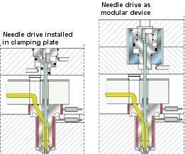
Figure 8: melt control in the coaxial valve gate.
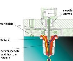
Figure 9: Core-back technology with coaxial needle valve nozzle for the production of a double-ply cup or sandwich cup.
Valve Gate for Multi-Component Applications
The coaxial valve gate was developed using the principles of the standard valve gate (see Figure 8). This technology allows the injection of two components via one injection point. The components may be injected both at the same time or delayed. Considering the mold technology the following layer configurations are possible: inner/outer or outer/inner layers (simple layers) or outer/inner/outer layers (sandwich). Both configurations can be molded with the same test mold for the production of a cup as shown in Figure 9. The possibility of using the sandwich method for direct gating in a multi-cavity mold especially opens up a wide range of applications. For example, the production of pre-forms with barrier layer or the production of parts with thick walls (foamed core component to counterbalance shrinking) is possible. The use of materials with different structures for the inner and outer layer helps to create special haptical appearances. An example is the production of a TPE-shift knob in a four-drop mold as shown in Figure 10.
In addition, the coaxial valve gate is suitable for partial hot runner solutions as well. For example, there are different methods that it can be used as a machine nozzle. The first one is the application as a "universal single nozzle" within an additional machine plate. This configuration allows the production of sandwich parts by using standard two-component machines in combination with conventional runner solutions (three-plate molds). In this case, the part as well as the cold runner system must have sufficient dimensions because due to the so-called "sandwich plate," a large portion of the mold daylight width cannot be utilized.
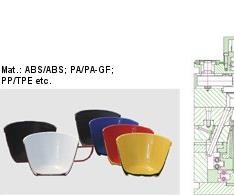
Figure 11: Coaxial valve gate as machine nozzle
This problem is eliminated when using a two-component machine nozzle (see Figure 11). In this case, a machine with special configurations must be used because both injection units must be connected with the coaxial valve gate nozzle. The coaxial valve gate system facilitates the injection of both components simultaneously. Adjusting the simultaneous phase of the injection cycle can vary the penetration of the core component. With a machine configuration as mentioned above, both injection units could be used independently for standard injection molding. For articles that must be molded in two different colors, the color change can be accomplished with only one shot.
Of course, two-component molding can be done with "conventional" valve gate systems as well. One of the methods normally used is the transfer method, requiring a rotary table or a handling system. The other method is the core-back method. Both are seldom used for layer configurations but mainly for production of articles with additional sealing lips, grip-areas and two colored areas positioned next to each other or injected polymer windows.


Related Content

Moldmakers Deserve a Total Production Solution
Stability, spindle speed and software are essential consideration for your moldmaking machine tool.
Read More
Treatment and Disposal of Used Metalworking Fluids
With greater emphasis on fluid longevity and fluid recycling, it is important to remember that water-based metalworking fluids are “consumable” and have a finite life.
Read More
Considerations for Mold Base Material Selection
Choosing the right material can greatly affect the profitability and cost of your application.
Read More
The Benefits of Hand Scraping
Accuracy and flatness are two benefits of hand scraping that help improve machine loop stiffness, workpiece surface finish and component geometry.
Read MoreRead Next

Are You a Moldmaker Considering 3D Printing? Consider the 3D Printing Workshop at NPE2024
Presentations will cover 3D printing for mold tooling, material innovation, product development, bridge production and full-scale, high-volume additive manufacturing.
Read More
Reasons to Use Fiber Lasers for Mold Cleaning
Fiber lasers offer a simplicity, speed, control and portability, minimizing mold cleaning risks.
Read More
How to Use Continuing Education to Remain Competitive in Moldmaking
Continued training helps moldmakers make tooling decisions and properly use the latest cutting tool to efficiently machine high-quality molds.
Read More