
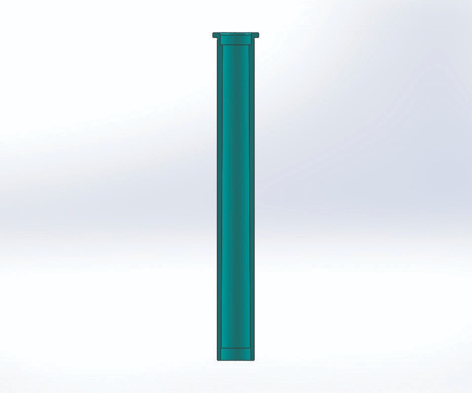
This polycarbonate part with an L/T (length-to-thickness) ratio of less than 65 and a final wall thickness of 0.027 of an inch (0.68 millimeter) was successfully injection-molded using a standard-sized bubbler. Images courtesy of DZynSource LLC.
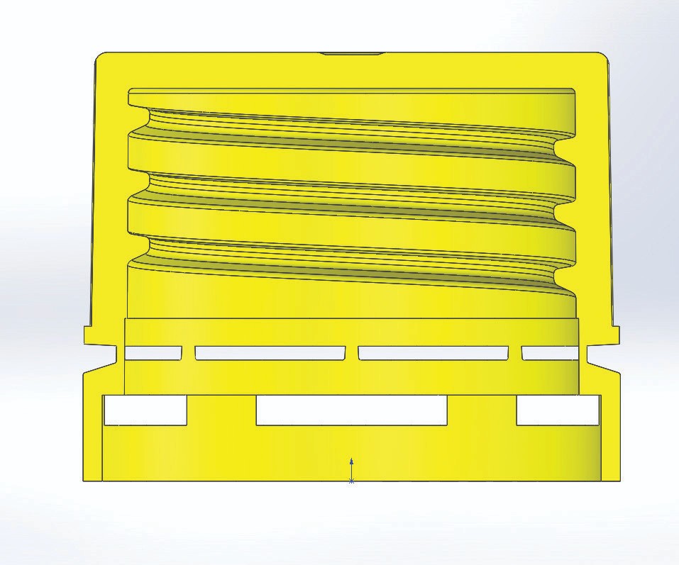
The tamper-evident band in this part, which has thick and thin sections, barely shrank. If a steel-safe adjustment is an economical option, then this may not be a problem. Mold design is critical here. Ask this question: If the molded part is too large in the area with the thin-wall section, can a steel-safe adjustment be made economically? If not, then go back to the larger bubbler and the lower heat-transfer rate. With a little advanced planning at the design stage, a moldmaker can make both optimized and standard bubblers and interchange them as required.


The plastics industry has been incorrectly sizing waterlines for years. This is most prevalent in mold designs that use bubblers to deliver the cooling medium. In the equivalent hydraulic diameter method (DH = 4A/P), “dh” is the hydraulic diameter, “A” is the area section of the passage, and “P” is the perimeter of the passage. Using this method to determine the correct bubbler size to maximize coolant flow rates increases water flow, reduces clogging and decreases cycle time. However, it also can have some unexpected, negative results.
Here are five reasons not to maximize coolant flow rates, especially when using bubbler tubes to cool the cores.


1. Incomplete cavity fill. When sizing bubblers using the equivalent hydraulic diameter method, the cooling is so drastically increased that thin sections of the part may freeze before the cavity filling is complete.
Figure 1 shows an example of a polycarbonate part with an L/T (length-to-thickness) ratio of less than 65 and a final wall thickness of 0.027 of an inch (0.68 millimeter). The moldmaker heated the mold for this part to 160–200°F and injected the polycarbonate at pressures up to 40,000 psi (pounds per square inch). Also, the part was valve-gated at the top flange. When the moldmaker installed an optimized smaller bubbler, the part froze prematurely and could not be filled. The optimized bubbler allowed fluid to pass through the bubbler/core circuit at a rate of 5 gallons per minute.
The part was injection-molded successfully using a standard-sized bubbler that gave equal area inside and outside of the bubbler. The standardized bubbler also greatly reduced the flow rate to 0.7 gallons per minute. The problem was not temperature. It was heat transfer.
2. Wide variation in shrinkage rates. In parts with thick and thin sections, there will be a wider difference in shrinkage rates. The thin sections of a plastic part cool very rapidly because of increased heat transfer that occurs when using bubblers sized with the equivalent hydraulic diameter method. The thick sections cool faster too, but the thin sections freeze so quickly that the expected shrinkage rate is not achieved. As a result, there may be very little shrinkage in the part’s thinner sections (see Figure 2).
3. Excessive flow rates. Larger parts that permit more room for increased cooling channel sizes can have excessive coolant flow in the mold. It is important for moldmakers to calculate the appropriate amount of cooling when incorporating the cooling system into the mold design. It can be expensive and wasteful to exceed the amount of cooling that is required.
For example, a moldmaker designed and built a 2 by 64 stack mold for a closure, with a 38-millimeter major diameter thread and a height of 0.400 of an inch inside the cap, without calculating the actual cooling requirements for the mold. The part was a 3-gram polypropylene cap with wall thicknesses in the 0.040–0.050 of an inch range and with maximized cooling. The moldmaker pumped water through the mold at 275 gallons per minute. The moldmaker calculated the amount of water that was necessary to remove the heat from these caps and discovered that the required minimum coolant flow was closer to 50 gallons per minute. Much energy was wasted pumping the excess water through the mold at 225 gallons per minute.
4. Molded-in stresses. When the cooling rate is not the same on both sides of a molded part, the result is molded-in stress. For example, when using semi-crystalline materials, the slower cooling side will form larger crystals that shrink more than smaller crystals, which results in excessive stress and warpage. Amorphous materials shrink more on the slower cooling side as well, and the corners of rectangular parts with sidewalls often cool last, which can cause parts to deform inward.
5. Gate freeze. When adding cooling to a cavity, sprue or gate insert, particularly with hot runner molds, moldmakers need to ensure that the cooling is appropriate, as the heated probe may not be able to supply enough heat to keep the gate open. The hot runner supplier can provide cooling recommendations and cooling design approval.
The bottom line is that moldmakers must put more engineering into mold designs to avoid the added expense and problems of over-designing and under-designing molds. The key is properly calculating the required amount and location of cooling.
About the Contributor
Rocky Huber
Rocky Huber is an engineering manager for Ivanhoe Tool & Die Co. LLC and owner of DZynSource LLC.


Read Next

Get More Coolant Flow Through Smaller Bubblers
This method for calculating the size of nonround water passages is designed to increase coolant flow, and reduce pressure loss and cycle time.
Read More
Are You a Moldmaker Considering 3D Printing? Consider the 3D Printing Workshop at NPE2024
Presentations will cover 3D printing for mold tooling, material innovation, product development, bridge production and full-scale, high-volume additive manufacturing.
Read More
How to Use Continuing Education to Remain Competitive in Moldmaking
Continued training helps moldmakers make tooling decisions and properly use the latest cutting tool to efficiently machine high-quality molds.
Read More