
Streamlining Roll Dimension Calculations for Mold Components
A new roll dimension calculator streamlines the use of roll pins to measure core pins, wedge blocks, shut-off surfaces or electrode details to determine the exact size of a workpiece’s angled detail.
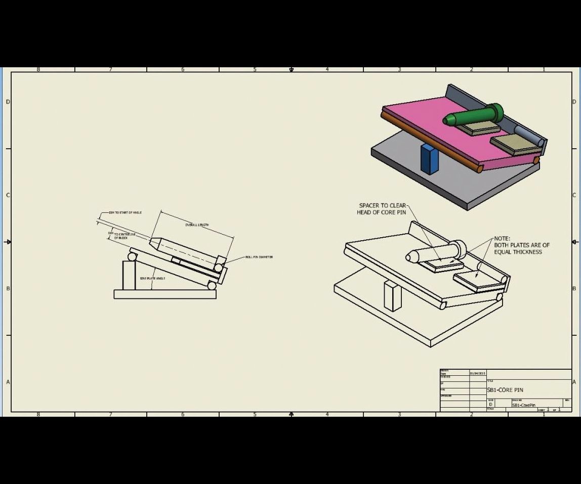
This is a typical setup for checking core pin details. Image courtesy of Moldmaking Resource.
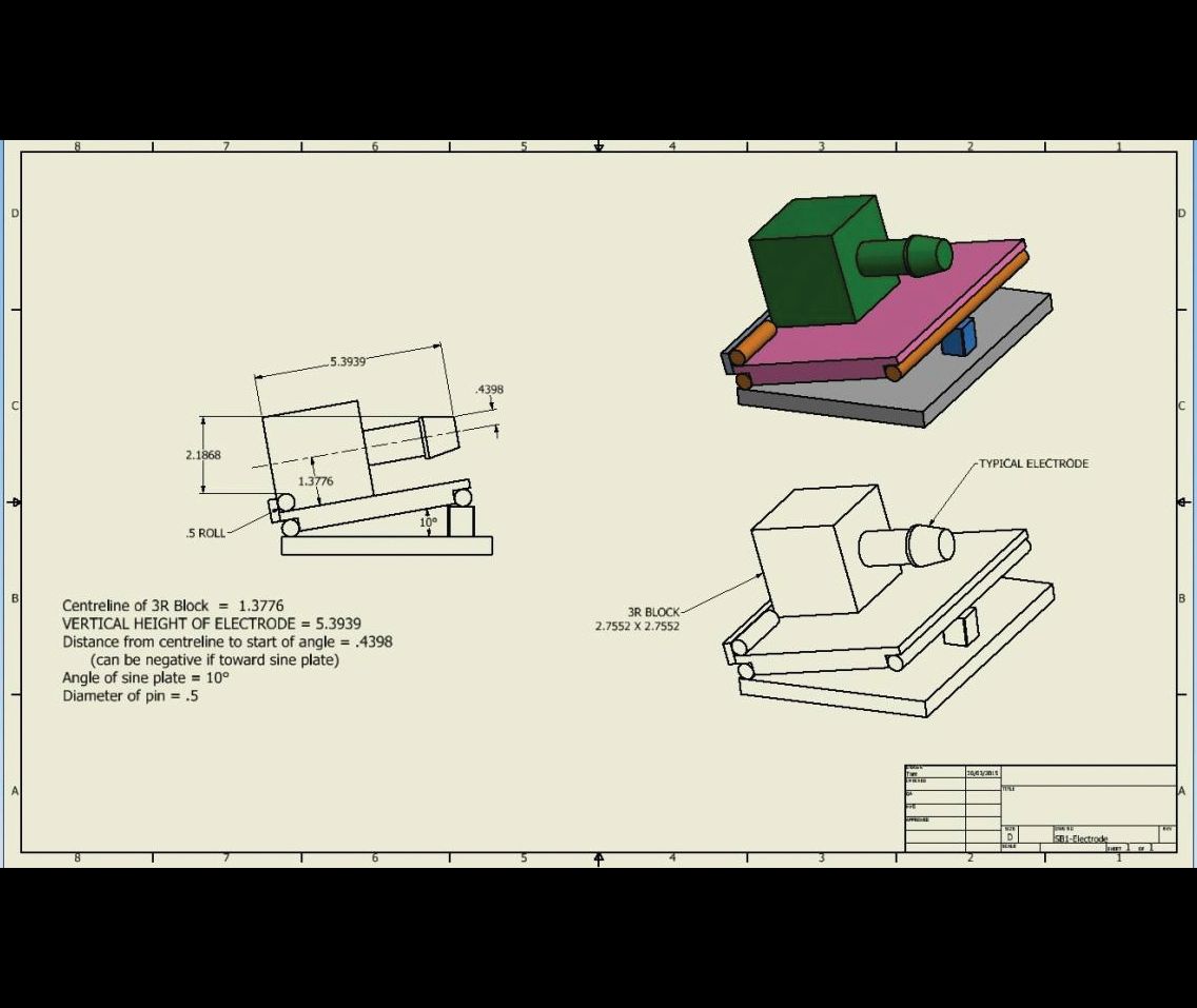
This is a typical setup for checking EDM electrode details. Image courtesy of Moldmaking Resource.


Today’s complicated molds and shorter deadlines almost make the old cut-and-dry method of moldmaking obsolete. Now specialists manufacture components to 0.0001-inch tolerances that fit together perfectly during assembly, although hand fitting is still required to assemble a complicated injection mold. Whether electrical discharge machining, milling, turning or grinding, moldmakers need a precise method to inspect workpieces. This is where using roll dimensions to measure critical mold components, such as core pins, wedge blocks, shut-off surfaces and electrode details is still the most effective way to determine the exact size of a workpiece’s angled detail.
Moldmakers need a surface plate, a sine plate, gage pins, a test indicator and a height gage or a gage block to use roll dimensions for moldmaking. An electronic height gage can replace the test indicator and gage blocks, if it is available. For accuracy, moldmakers need to ensure that all of these tools are calibrated and repeatable.


Manually generating roll dimensions is a time-consuming process, but today that process can be streamlined with a desktop, roll dimension calculator app that takes a few pieces of information and instantly calculates the required roll dimension without trigonometry. Roll dimension calculator apps are plug-and-play apps, but they do require some practice to fully utilize. They can save hours of calculations and simplify the machining process. Anyone who is familiar with Excel can easily input the formula and create a custom application to quickly calculate the math required for a roll dimension. The key is making sure that every department uses the same measurement process. All too often, the grinding department is using one method and the milling department another.
Follow these steps:
- Gather the necessary information, and enter it into the calculator and press calculate.
- Record this number.
- Set up the sine plate on the appropriate angle.
- Place the correct diameter roll pin (or gauge pin) in the corner of the sine plate against the back rail, as shown in the two examples. If a moldmaker is checking something such as a core pin with a head, he or she must use parallels in the setup. Moldmakers should be sure to use the same size parallel under the roll pin as is under the core pin.
- Measure from the surface plate (or the bottom of the sine plate) to the top of the roll pin, and record.
- Add the number from Step 2 to the number from Step 5. This is the target dimension.
- Machine the component to the target dimension.
Some shops include roll dimensions in the CAD drawings, which is a great timesaver. However, what happens when a dimension changes during the machining process? This is particularly relevant when machining EDM electrodes, for example. The overall height is typically a random dimension and requires a modified roll dimension, if the height is different from the CAD drawing. With the roll dimension app, a moldmaker can obtain a new target dimension in seconds simply by changing the height in the app.


Related Content

When to Use Solid Carbide Thread Mills or Indexable Thread Mills
Pointers for choosing solid carbide thread mills versus indexable thread mills.
Read More
How is an Aluminum Mold Energy-Efficient?
Nine ways aluminum molds save energy and production costs.
Read More
How to Eliminate Streaks and Weld Problems with Laser Technology
Laser technology overcomes streaking and welding challenges for new mold textures and texture repair.
Read More
How to Produce More Accurate Molds and Reduce Rework
Patented micro-milling process for manufacturing steel plate flat and parallel helps mold builders shorten mold build times and increase accuracy.
Read MoreRead Next

Reasons to Use Fiber Lasers for Mold Cleaning
Fiber lasers offer a simplicity, speed, control and portability, minimizing mold cleaning risks.
Read More
How to Use Continuing Education to Remain Competitive in Moldmaking
Continued training helps moldmakers make tooling decisions and properly use the latest cutting tool to efficiently machine high-quality molds.
Read More