
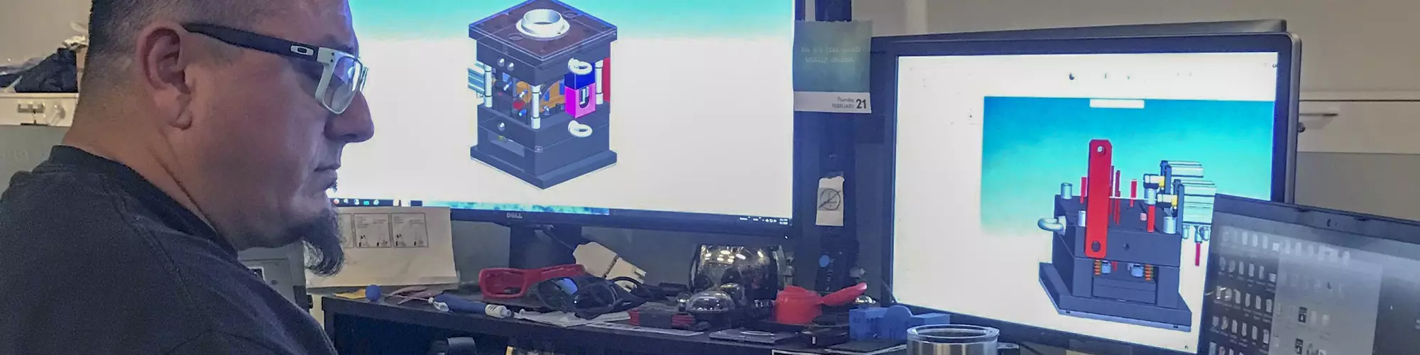


Today, Gerardo (Jerry) Miranda III is the senior global mold and process engineer for Apple, but when he was the global tooling manager for Oakley sunglasses, he shared some essential steps from his mold design checklist. These insights are still relevant today, so we are bringing back the complete checklist to illustrate the extent to which it can impact your product time and cost-to-market process.
Designing a mold may involve working with cross-functional teams to initially ensure product manufacturability, but in the end, it comes down to the mold designer who must execute a perfect CAD drawing for moldmakers to follow. Source | Oakley.
Having a proper tool design review and checklist can and will save time to market. An essential component is a tool design team that works across functions by performing design for manufacturability (DFM) throughout the entire process — from sketch and design engineering through CAD. This means when final product CAD is released to the tool design team, there is little to no request for iterations to enable a robust tool design.


The next step of tool design is designated to one person who takes that CAD and wraps a tool around it. The general design direction has already been determined by several CAD reviews and discussions with team members, so this person is responsible for managing cost, manufacturing difficulties and ensuring the design stays within the confines of the desired press size. If executed correctly, this task can save time in the manufacturing of the tooling, as well as initial tool startup time and qualification.
With typical tool designs taking 3-6 weeks to execute, high-level decisions and innovations are implemented quickly — extra care must be taken to ensure that smaller details are not overlooked. Tool design is like a soup. The designer has ensured that the movements required by part geometry are designed in (the meat) and the part has a gate to fill the part (the vegetables), and the tool fits in the press (the broth). Then the cavity and core blocks need the proper number of screw holes to retain it in the base (the soup bowl).\
A tool design checklist can be reviewed by the tool designer as he/she works through the design. It can be documented and reviewed with cross-functional manufacturing teams before final tool design release to the build shop. These teams should include, but are not limited to process engineering, automation, tool maintenance and post-mold operation (PMO) teams, including representation from assembly and secondary teams such as paint and/or decoration teams. All team members should have knowledge of desired end product needs and review the tooling for their individual needs — for example, does the tool design allow for end-of-arm to be used to remove a part from tool via a picker feature or does the tool incorporate a feature for the paint team to handle the part in their line?
We have asked for no-fly zones and design needs from each of these teams and incorporated them into our tool design standards. This has decreased the time spent at tool startup and product launch. Below is an example of what we have implemented into our design checklist:
- Does the tool fit in the desired press?
- Is the base material proper for the class of mold ordered?
- Are mold components made of proper materials?
- Will the part stay on the proper side of the mold for ejection?
- Have mold inserts been reviewed for manufacturability?
- Are runners the proper size? Is the gate size and location correct?
- Is the sprue puller correct? Does the Z puller pin have a ring vent?
- Are runner shutoffs needed?
- Are cooling lines/heater rods sufficient and appropriate to the material?
- Is a thermocouple required?
- Are insulator sheets needed?
- Are the water/oil fittings size and style correct?
- Are parting line side locks or taper locks necessary and protect shutoffs?
- Are there enough ejector pins, blades and ejection sleeves?
- Are there adequate support pillars and stop pads? Is guided ejection needed?
- Is ejection stroke sufficient and does it clear the part from the mold?
- Is a positive spring ejection return needed?
- Does the mold need to be tied to an ejection unit?
- Is a switch needed to verify ejection?
- Is an air blast and/or other ejection assist needed to clear the part from the mold?
- Is slide and/or lifter travel enough to clear when the part is ejected?
- Are slides held in open position effectively?
- Are cavity and part identifications and date codes needed and in the proper size and location?
- Has venting been addressed?
- Is there proper mold base relief?
- Are mold components poka-yoked (mistake-proofed) and/or keyed for proper assembly and timing?
- Are moving components checked for collision, clearance and orientation?
- Is a quick change mold system to be used in-press and will the mold fit?
- Are clamp slots or machine mounting holes correct and sufficient to hang the mold in the press?
- Are there enough and correct eyebolt holes?
- Is the mold safety strap in the proper location?
- Is the locating ring diameter, sprue busing orifice and radius correct?
- Are knock-out locations and sizes correct?
- Is the mold’s identification and weight shown correctly and in the proper location?
- Are there enough pry bar slots?
- Are leader pins taller than any other mold components above the parting line?
- Is the surface finish defined in the mold design drawings?
- Is proper tolerance defined in the detail drawings for dynamic and static fits?
Further Steps to Take Before Beginning to Design
Not necessarily part of the tool design review, but rather part of the DFM, are a few items to be considered before a tool design is started.
- Is there adequate draft for the desired texture and part geometry?
- Is part geometry considered when developing the parting line in the part?
- Is the part influenced to stick in the correct side of the mold, considering which side of the part can or cannot have ejector pin marks?
Another constraint that should be looked at is the press tonnage sourced. As a quick check to ensure the press size can be utilized, I have found this rule of thumb helpful: Take the square inch area of the part by measuring the extreme length and width of the part size as projected on the parting line and multiply by the following values to calculate required clamp tonnage, using the higher value for thinner walled parts and the lower value for thicker, more even part geometry (see matrix below). This is usually dictated by the customer via press capacity and scheduling demands.


Related Content

Thoughts on VR's Immersive, Interactive Mold Design Training
A virtual reality (VR) application transforms training from passive to active learning by immersing users in a dynamic virtual space.
Read More
Tackling a Mold Designer Shortage
Survey findings reveal a shortage of skilled mold designers and engineers in the moldmaking community, calling for intervention through educational programs and exploration of training alternatives while seeking input from those who have addressed the issue successfully.
Read More
SURVEY: Assessment to Determine Demand and Supply for Skilled Mold Designers
What are the current and future states of mold designers and their training? Tell us!
Read More
On a Mission to Develop Mold Designers
Editorial Advisory Board member Nicholas Vitelli—a lecturer in the Plastics Engineering Technology Program at Penn State Behrend— discusses the need for better-trained plastics engineers and mold designers to help businesses solve problems.
Read MoreRead Next

How to Learn Mold Design Virtually
Plastics Engineering program instructors share their strategies for successful virtual learning for hands-on injection mold design.
Read More
How to Manage Wall Thickness Changes in Your Mold Design
To ensure even filling and cooling, consider wall section transitions, corners and fillets, ribs and bosses, lip and rim designs and CAE flow simulation software.
Read More
It Starts With the Part: A Plastic Part Checklist Ensures Good Mold Design
All successful mold build projects start with examining the part to be molded to ensure it is moldable and will meet the customers' production objectives.
Read More