
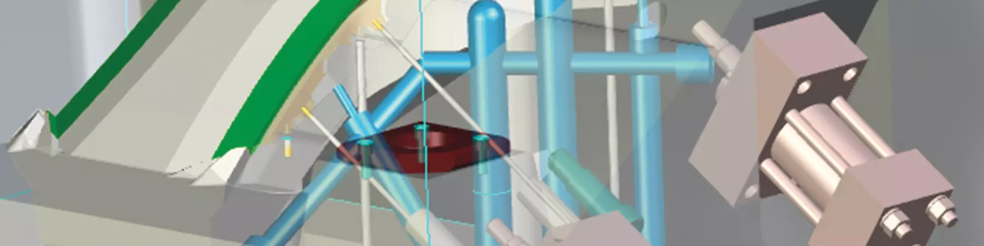


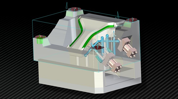
Hydraulic cylinders provide mold designers and molders with opportunities for improved performance and flexibility. Extending actions beyond the mold base and pulling slide cores at complex angles can simplify design, reduce mold size and decrease cost per part. Proper cylinder sizing is critical to performance. The use of hydraulic locking cylinders often provides more capability in a smaller footprint, thus enhancing these effects. Image courtesy of Manuel Martinez, Absolute Tool Technologies.
When considering an actuator for an injection molding application, review three positions to determine the impact on cylinder type and capacity: initial breakaway, movement through the stroke, and final positioning. Physical force requirements for each (both set and pull) will provide insight into the most limiting conditions and direct selection of the most appropriate product type. Determine limiting forces, then determine size.
Core Set Considerations
For most moveable core applications, initial movement and core weight forces are very low relative to the force needed to preload the slide during injection. For applications holding the core with a heel block, choosing cylinder size for only movement and lift reduces cylinder requirements significantly. Preloading the movable core in the set position hydraulically without a lock can be problematic, as any amount of exposed molding surface creates increased force requirements and requires larger cylinders and dedicated hydraulic pressure during injection. Available hydraulic flow in gallons per minute (gpm) from the press or auxiliary pump may be insufficient to provide adequate cylinder speed, especially for longer strokes.


Consider alternatives such as preloading hydraulic locking cylinders. With very high output force in the set position, these cylinders typically have much smaller bore sizes, lower hydraulic requirements, and higher speeds.
As some presses remove hydraulic pressure to core circuits during injection, the use of hydraulic cylinders without a heel block or preloading locking cylinder may not be possible. For presses that drop hydraulics, ensure locking cylinders maintain preload after locking without pressure or that an independent hydraulic source is available. Some customers use check valves with standard hydraulic cylinders. However, this adds complexity, and without a dedicated hydraulic supply, check valves may pass some fluid, and pressure may drop.
When considering an actuator for an injection molding application, review three positions to determine the impact on cylinder type and capacity: initial breakaway, movement through the stroke, and final positioning.
Core Pull Considerations
Initial force to pull is sometimes demanding due to material shrinkage around the core or if the core is set into a shallow taper with preload. Once initial retract movement occurs, the remaining stroke and hold in the final pull position usually requires low forces that are not limiting. To reduce overall breakaway forces, providing tapers over eight degrees or a slight touch or gap to the taper using a core stop to absorb preload and time the final position is helpful.
Long, penetrating cores with aggressive shrinkage will likely create a limiting condition and require larger bore hydraulic cylinders to pull them free, unless an internal diameter taper can be added to the part to improve release. When using preloading hydraulic locking cylinders, use caution, as many provide large output forces but low retract forces. Larger bore models may be available from some manufacturers to accommodate breakaway demands when retracting the core.
Mold Forces from Injection and Shrinkage
Force on the slide core due to injection (Fi) is a function of the nozzle injection pressure (P) and the core exposed surface area projected along the axis of movement (Ap).
Fi=Ap x P
For fully exposed cores, the projected area is best visualized by thinking of slicing the core perpendicular to the direction of movement and measuring the resulting region.
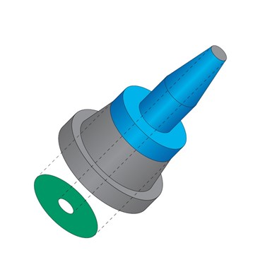
The area of a movable core is the area exposed to plastic (blue surface) projected along the core axis onto a perpendicular plane (green surface area). The projected area is typically much less than the exposed surface area. Shutoffs are often excluded from force calculations but should be considered as a potential overload force on the core if flash occurs.
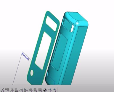
Information on how to use CAD systems to calculate the projected area for complex surfaces is available online – see a video example from SOLIDWORKS – Surface Area Projection YouTube Go Engineer, which demonstrates selecting the object surfaces, removing cutouts and projecting onto a plane.
While it is possible that some pressure drop will occur in the cavity and pressure at the core may be less than nozzle pressure, it is often as likely that peak pressure will increase due to processing demands. Cavity pressure is sometimes difficult to predict, even with mold flow analysis, so using nozzle injection pressure is recommended.
After injection, the plastic part cools and may shrink around the core, developing friction that resists movement. Calculating the resisting force Fr is more challenging and seems to be highly dependent on plastic material type and amount of cooling. (Note: Some historic calculations have been used with varying degrees of success and may be available from other sources.)
Cylinder Extend and Retract Forces
The formula for force (C) from a hydraulic cylinder is the differential area (D) multiplied by the hydraulic pressure (H) core pull circuit system machine pressure.
C = D x H
The term differential area is used to remind us to subtract rod area for retract calculations. The differential area (D) for extend (De) is the area of the cylinder bore De= 3.14xB2/4, where B is the bore diameter and determines the extend force Ce. The differential area for retract (Dr) is the “difference” in areas between the bore and rod Dr =3.14x(B2- R2)/4 and determines the retract force Cr.
To prevent core movement during injection, the cylinder extend force (Ce) must exceed the injection force (Fi). To ensure core pull, the cylinder retract force (Cr) must exceed the resistance force (Fr).
Hydraulic locking cylinders provide separate locking at end of stroke, which may lock only and provide no additional force or may be of the preloading style that may provide much larger extend forces. Preloading hydraulic locking cylinders with large output extend forces have an extend force (K) at end of stroke, but function as typical cylinders for retract with force (Cr). For success:
Ce or K >> Fi and Cr >> Fr
Sizing a cylinder with hydraulic force (Ce) or preload force (K) greater than the calculated injection force (Fi) is necessary to prevent movement. Selecting a standard cylinder with a bore diameter and available hydraulic pump pressure combination that exceeds this amount plus a safety factor of 15 to 30% (SF = 1.15 to 1.30) is desirable to account for 5-10% of system losses and perhaps 10-20% for unexpected changes in injection pressure.
Sizing a cylinder with hydraulic force (Ce) or preload force (K) greater than the calculated injection force (Fi) is necessary to prevent movement.
Cylinder Selection
With the formulas mentioned earlier, the injection force (Fi) can be calculated and multiplied by the safety factor (SF) to determine the necessary cylinder force (Ce) or preload force (K) for core set. Cylinder retract force (Cr) can then be evaluated for effectiveness relative to the estimated friction force (Fr) to pull the core from the pocket.
Calculating forces for a variety of cylinders and solving for minimum bore size is possible; however, using the chart below is often easier and provides some comparisons of relative size. Note the large preload forces from the hydraulic locking cylinders (HLC), which are six to ten times that of standard cylinders of the same bore diameter at 1500 psi hydraulic pressure.
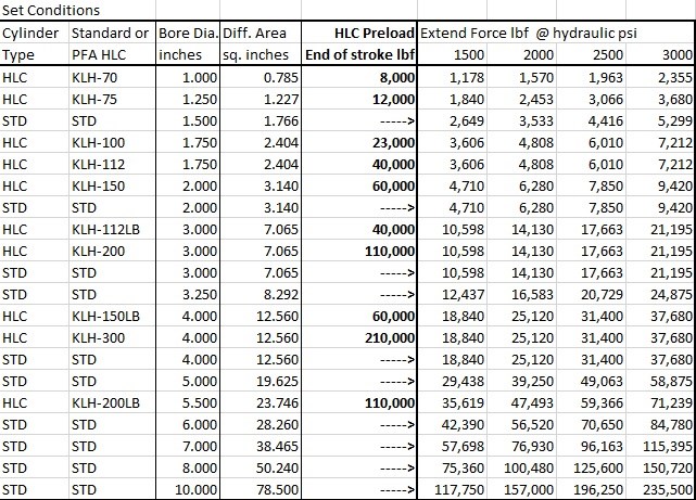
For example, extend preload force of 40,000 lbf (20 ton) in a 3-inch bore hydraulic locking cylinder would require a 6-inch bore standard hydraulic cylinder. The standard cylinder force is only available if hydraulic pressure is maintained. In all but the smallest applications, hydraulic locking cylinders provide a large force and size advantage to standard cylinders.
Cylinder retract or pull force is always less than extend or set force due to reduced piston area. Oversized rods in HLC cylinders provide greater preload capacity and are allowable for most applications. However, for long cores with significant plastic shrinkage, a larger bore may be necessary to provide sufficient pull force. Click this ONLINE ARTICLE LINK for a more detailed chart of sizes and pressures.
Pull force in hydraulic locking cylinders is much less relative to the larger bore standard hydraulic cylinders. When using a standard cylinder, the pull force is often capable of pulling the core, while when using a hydraulic locking cylinder, penetrating cores may be more problematic. In most cases, however, parts do not have significant part penetration and pull forces are relatively low or can be reduced by increasing draft or adding stops to the core.
For best results, consider all the stroke positions of the cylinder, both set and pull, and calculate forces. Choose the best preload, bore and rod combination that meets all requirements, ensuring pressure is available to the cylinder during injection, as appropriate.


Related Content

Maintaining a Wire EDM Machine
To achieve the ultimate capability and level of productivity from your wire EDM on a consistent, repeatable and reliable basis, regular maintenance is a required task.
Read More
Treatment and Disposal of Used Metalworking Fluids
With greater emphasis on fluid longevity and fluid recycling, it is important to remember that water-based metalworking fluids are “consumable” and have a finite life.
Read More
Hands-on Workshop Teaches Mold Maintenance Process
Intensive workshop teaches the process of mold maintenance to help put an end to the firefighting culture of many toolrooms.
Read More
Fundamentals of Designing the Optimal Cooling System
The right mold components can help improve mold cooling and thereby produce higher-quality parts.
Read MoreRead Next

Modular Side-Action System in Medical Part Molding Reduces Downtime, Cycle Times
Case Study/Mold Components, Medical.
Read More
How to Use Hydraulic Locking Cylinders to Improve Plastic Injection-Molded Part Profitability
Improve complex injection-molded part quality and profitability by reducing mold base size and preloading slides from a solid structure to ensure placement.
Read More
Reasons to Use Fiber Lasers for Mold Cleaning
Fiber lasers offer a simplicity, speed, control and portability, minimizing mold cleaning risks.
Read More