
Will This Part Clean Up?
To improve your manufacturing processes upstream and downstream, consider CAD data and 3D digitizing for lean layout and scrap reduction.
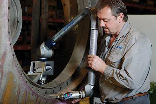
Most critical, pre-finished components are subject to various forms of inspection or layout. Here, a portable measurement arm is used to measure hole diameters on a large part. Images courtesy of Faro Technologies.
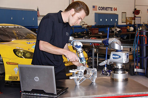
The use of CAD data and 3D digitizing technology can significantly improve overall inspection and layout accuracy, effectiveness and efficiency. Pratt & Miller Engineering uses portable measurement and contact inspection on parts for the Corvette Racing program.


Manufacturers who supply or receive pre-machined manufactured components, including molds, often ask, “Will this part clean up?” Molds, castings, forgings and pre-fabrications of all types, sizes and complexities are subject to this critical question. In fact, many of these parts have prints littered with dimensional data, geometric dimensioning and tolerancing (GD&T) and critical call-outs. Oftentimes, the question of part clean-up can make or break an order, a job or a delivery schedule, and although the respondent can vary from a supplier to the downstream customer or both, the question must be answered.
Achieving a confident answer through inspection and layout activity is often a difficult and time-consuming process. However, the use of CAD data and 3D digitizing technology can significantly improve overall inspection and layout accuracy, effectiveness and efficiency, resulting in the potential answer to this critical question.


Inspection Criteria
Most critical, pre-finished components are subject to various forms of inspection or layout. As manufacturers continue to strive for nearer-net-shape molds, castings, forgings and fabrications, this process becomes more detailed and subject to scrutiny. A shop that receives a mold may spend a great deal of time and employ several different methods to ensure the mold’s dimensional integrity. This may include use of height gages, layout machines, calipers, dial indicators, fixed CMMs, portable CMMs and more. There could be dozens of complex inspection criteria (e.g., diameters, positions, angles, etc.) that must be satisfied before components are acceptable to the customer and viable for post-processing.
Satisfying all of the inspection criteria can create the following issues:
1. Difficulty in conducting proper inspection, requiring multiple tools, tolerance stack-ups, etc.
2. Multiple interpretations of inspection data by the supplier and customer, leading to discrepancy.
3. Multiple (and differing) inspection methods used by the supplier and customer.
4. Significant non-value-added time in the part’s value stream, increasing overall lead time.
5. Errors that can lead to unnecessary part rejection, scrapping of parts once on the machine and unnecessary re-work.
6. Unnecessary addition of safety stock on components to ensure their acceptance. This can also generate unnecessary waste in raw material, increased energy required to provide pre-finished components and additional material removal.
A Digitizing Solution
These potential issues have driven manufacturers to search for a more effective inspection/measurement solution. One technique being rapidly adopted is the use of finished-part CAD data in conjunction with a 3D digitizer (laser scanner, photogrammetry, imaging systems, CMM with rapid-probing, etc.). The 3D measurement system can be used to collect data in all critical areas of the supplied component, then 3D measurement software is used to compare this collected data to the finished part model. This is a slight variation from the traditional methodology of comparing a pre-finished part to its pre-finished model (or print). However, comparing to finished geometry allows the supplier or customer to quickly and clearly see where the pre-finished component is heavy or short.
Most of today’s 3D software packages make it readily apparent where the supplied component has either too much or too little stock. This could also be visually apparent in a part that may simply require a re-alignment.
Too much stock. This can lead to wasted machine hours and unnecessary material scrap. It could also be an indication that the upstream process (mold, casting, etc.) needs to be altered to reduce excess raw material (reducing costs and scrap, etc.). At the very least, the excess stock can be accounted for in the shop’s schedule and in the lead time given to the customer.
Too little stock. This could mean that the ideal finished part will not be realized from the supplied component, so the component should not be set up on the machine to avoid generating a scrapped part. It could also mean that the component must go through remediation before it can be post-processed. Either way, the parties involved have a heads-up on this condition and can make decisions without incurring further scrap or delays.
Re-alignment/re-layout. If the part analysis to CAD shows heavy in some areas and light in others, there may be an opportunity to save these components by digitally re-aligning the part to the CAD. Many available software packages (with varying degrees of ease and effectiveness) can digitally best-fit the collected part data to the finished CAD model. This can transform a part that was considered in failing condition and allow it to proceed through the value stream.
In fact, some available 3D digitizers can be used to identify the new, ideal setup locations for machining. The digitizer can determine and often even scribe the key setup locations onto the part, ensuring proper setup downstream and proper clean-up.
Answering the Question
The amount of data, and ultimately the 3D hardware/software solution, required to get a good part analysis to CAD will vary from part to part, based on geometry, complexity and tolerance. However, employing CAD data and 3D digitizing can be a fast, effective and almost error-proof solution for suppliers and downstream manufacturers. So, to answer the question, “Will this part clean up?” and improve manufacturing processes upstream and downstream, consider 3D digitizing. It can lead to lean layout and scrap reduction.


Related Content

Portable Low-Heat, Non-Arcing Resistance Welder for Mold Repair
Rocklin’s user-friendly MoldMender Micro Welder delivers simple and cost-effective localized repair in-house with precision and versatility, enhancing mold and die durability and reducing disassembly and downtime.
Read More
Hands-on Workshop Teaches Mold Maintenance Process
Intensive workshop teaches the process of mold maintenance to help put an end to the firefighting culture of many toolrooms.
Read More
Predictive Manufacturing Moves Mold Builder into Advanced Medical Component Manufacturing
From a hot rod hobby, medical molds and shop performance to technology extremes, key relationships and a growth strategy, it’s obvious details matter at Eden Tool.
Read More
What is Scientific Maintenance? Part 2
Part two of this three-part series explains specific data that toolrooms must collect, analyze and use to truly advance to a scientific maintenance culture where you can measure real data and drive decisions.
Read MoreRead Next

Inspection/Measurement Advances Yield Better Molds Faster
A roundtable discussion of the latest trends and developments in mold inspection and measurement technology highlights the cycle time reduction, accuracy improvement and cost decrease benefits.
Read More
How to Use Continuing Education to Remain Competitive in Moldmaking
Continued training helps moldmakers make tooling decisions and properly use the latest cutting tool to efficiently machine high-quality molds.
Read More
Reasons to Use Fiber Lasers for Mold Cleaning
Fiber lasers offer a simplicity, speed, control and portability, minimizing mold cleaning risks.
Read More