
Validation of Design Guidelines
Flow simulation software integrated with powerful 3-D CAD functionality can be effectively and efficiently applied to validate guidelines for cooling time and runner sizing.


Runner length guidelines. Optimize runner length and verify pressure drop.
Runner diameter guidelines. Optimize runner diameters and verify pressure drop.


Mold material guidelines. Change mold material and analyze change in thermal distribution.
Integrated CAD-flow simulation approach enables user to reach solutions faster. Figures courtesy of VISI Flow.
Part design guidelines. A. Change part design. B. Determine required cooling time. C. Analyze part warpage. Part design can be easily changed and analyzed.


Gate geometry guidelines. Optimize gate design and check for excessive shear stress.

Cooling layout guidelines. Change cooling channel layout and analyze change in surface temperature of core and cavity.
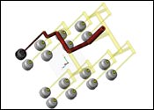
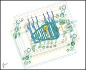
The current global competitive environment does not afford moldmakers the luxury of carrying out bench tests and molding trials to validate their guidelines. They usually rely on past experience to establish some of these guidelines. This article discusses how flow simulation software integrated with powerful 3-D CAD functionality can be effectively and efficiently applied to validate guidelines for cooling time and runner sizing (see Figure 1).
Cooling Time
A common challenge faced by moldmakers is to produce acceptable parts with minimum cycle time. As cooling time accounts for most of the cycle time, reducing the cooling time of a part will considerably reduce the cycle time. However, reducing the cooling time also may result in problems, such as excessive part warpage, high part temperature at the time of ejection, etc.


The minimum cooling time required to produce acceptable parts depends on many factors such as part geometry, plastic material, mold material, cooling layout and melt temperature. Before manufacturing the production tool, the moldmaker needs to understand how these factors would simultaneously affect cooling time and part quality.
For example, the moldmaker may seek to set guidelines on factors such as part thickness, material grade selection and number of cooling channels. Flow simulation software allows the designer to change these factors and study the influence of these factors on cooling time. The following guidelines for cooling time can be validated using flow simulation (see Figures 2a,b,c).
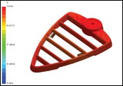
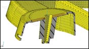
Part Design Guidelines
The moldmaker can create several part models using the CAD functionality of flow simulation software or in an external CAD software. A filling, holding and shape analysis can be carried out on each of these models. Simulations results such as pressure, temperature at the end of cooling, warpage, etc. would indicate if the part model would be acceptable or not. Based on these results, the moldmaker can optimize the part design to minimize cooling time.
Design changes are carried out very easily in flow simulation software that is integrated with powerful CAD functionality. The integration reduces the steps involved in analyzing design changes and also eliminates problems involved in importing and exporting models to and from external CAD software (see Figures 3a,b).
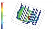
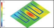
Cooling Layout Guidelines
An array of cooling layouts can be created and analyzed inside flow simulation software that has thermal analysis functionality. The cooling layout can be optimized to minimize cycle time based on the results of such a thermal analysis. The effects of cooling layout on part warpage also can be studied by running a thermal, filling, holding and shape analysis. It also is possible to set guidelines on variables such as coolant flow rates, cooling channel diameters and coolant temperatures to minimize cooling time.
It is quite tiresome to make cooling layout changes and analyze these changes if the mold is designed in an external CAD package. Flow simulation software with integrated mold design capabilities and automatic cooling channel mesh generation functionality greatly reduces the time and effort required to analyze cooling layout changes. In the past it would take several hours or even days to run thermal and warpage analyses. Flow simulation software has become much faster and does not require expensive computers to run analyses. These analyses can now be run in minutes even on standard desktop computers and laptops (see Figures 4a,b).
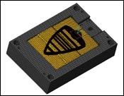
Mold Material Guidelines
Moldmakers quite often use mold materials of varying thermal conductivities to lower cooling time. For example, a copper alloy core insert may be used to extract the heat faster from the part. Flow analysis software allows the user to utilize the CAD model of the mold plates and then change the mold material. To save computer memory usage and to make simulations faster, flow simulation software allows the user to create different size mesh on the mold components. For example, a coarser mesh can be created on a mold plate while using a fine mesh on the mold insert. Using this approach, the moldmaker can analyze the effect of mold material, cooling layout and mold insert design on cooling time.
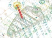
Runner Sizing
Runner sizing is a very important decision for a moldmaker. In hot runners, the moldmaker may seek to minimize the runner diameters in order to reduce melt residence time, reduce color change cycles or allow tighter pitch for drops. In cold runner molds, smaller runners mean lower material wastage. However, smaller runners in hot and cold runner molds may lead to excessive pressure drop. Very thick cold runners also may lead to an undesirable increase in cooling time.
Pressure drop of a tool depends on many factors such as runner geometry, plastic material, melt temperature, injection velocity, part geometry, etc. Once the runners are machined, it may prove to be very expensive and sometimes impossible to change these factors to reduce the pressure drop. In hot runner molds it is often required to select the product line. If the wrong product line is selected, the consequences could be catastrophic and may require manufacturing a brand-new expensive hot runner system.
These factors can be easily changed in flow analysis software to determine the pressure drop of the system and identify potential problems. The following guidelines for runner sizing can be established using flow simulation (see Figures 5a,b).
Runner Diameter Guidelines
Small changes in runner diameters can considerably affect the pressure drop. Flow analysis software allows the user to change runner diameters and analyze the effects of these changes on the pressure drop. The user has the option of defining runners on a curve or using the 3-D geometry of the runner. Functionalities that automatically detect the runner diameters inside a 3-D mold model and automatically create a runner mesh greatly reduce the time required to analyze different runner diameters (see Figures 6a,b).
Runner Length Guidelines
In some cases, moldmakers have to use long hot runner nozzles inside their tools. This problem may be compounded by a valve pin inside a small nozzle bore. In other cases such as in stack molds, the length of the runner system to the cavity may be excessively long. Using flow simulation, the moldmaker can determine if such designs may lead to excessive pressure drop. If there is excessive pressure drop, the moldmaker can make design changes to reduce the pressure drop to an acceptable value. For example, the runner diameters can be increased to compensate for the large runner length (see Figures 7a,b).
Gate Geometry Guidelines
Large gates often lead to undesirable gate vestige and the moldmaker often has to make the gate as small as possible. Small gates may lead to excessive pressure drop and excessive shear rates that may degrade the plastic. Using flow simulation, the moldmaker can optimize the gate design by analyzing different gate geometries under various molding conditions. The pressure and shear rate results will indicate whether or not the design is acceptable.
Summary
An optimized cooling design and runner design can significantly increase the productivity of a mold. By validating the design guidelines moldmakers can reduce or even eliminate the potential problems that may be faced by their customers.
Flow simulation software is a powerful tool that can be used to by moldmakers to validate design guidelines and also identify potential problems before the tool is manufactured. Flow simulation software packages are becoming more cost-effective and user-friendly. New functionalities have been added (see Chart 1) to make the simulation setup process easier and faster.
| Chart 1 | |
| Features/Functionality |
Advantages |
| 3-D mesh | Accurate results and fast model setup |
| Fast simulation speed | Reduce analysis time |
| Integrated CAD functionality | Fast design changes |
| Integrated machining functionality | Fast transfer of optimized design to manufacturing |
| Auto-cooling channel mesh conversion | Fast model setup |
| Auto-runner detection inside 3D mold model | Fast model setup |
| Assign repetitions to runner segments | Reduce setup and analysis time |
| Useful functionality in flow simulation software for establishing guidelines for cooling time and runner sizing. | |


Related Content

OEE Monitoring System Addresses Root Cause of Machine Downtime
Unique sensor and patent-pending algorithm of the Amper machine analytics system measures current draw to quickly and inexpensively inform manufacturers which machines are down and why.
Read More
Tolerancing in Mold Design, Part 2: Using GD&T to Address Conventional Tolerancing Issues
Mold designers can achieve a single interpretation of workpiece functionality when following the American Society of Mechanical Engineers Geometric Dimensioning and Tolerancing standard.
Read More
How to Manage Wall Thickness Changes in Your Mold Design
To ensure even filling and cooling, consider wall section transitions, corners and fillets, ribs and bosses, lip and rim designs and CAE flow simulation software.
Read More
MoldMaking Technology's Most-Viewed Content 2022: Products
MMT shares the five top-viewed technologies, equipment and services of 2022 in each Engineer, Build, Maintain and Manage tenet based on Google Analytics.
Read MoreRead Next

Staying Competitive Using Mold Flow Analysis
The pressure on the supply chain is unrelenting for all things faster, better and cheaper. For moldmakers, getting molds built right the first time is critical to meeting these increasing demands. But how?
Read More
Reasons to Use Fiber Lasers for Mold Cleaning
Fiber lasers offer a simplicity, speed, control and portability, minimizing mold cleaning risks.
Read More
Are You a Moldmaker Considering 3D Printing? Consider the 3D Printing Workshop at NPE2024
Presentations will cover 3D printing for mold tooling, material innovation, product development, bridge production and full-scale, high-volume additive manufacturing.
Read More