
Using Simulation to Locate and Size Gates
Considerations and trade-offs when determining proper gate locations with simulation, which helps all stakeholders make a sound decision based on the priorities of the project.
Molded samples of the Annunciator part confirmed the predicted fiber orientation and warpage of the part.
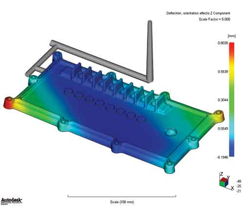
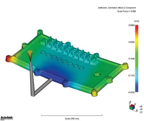
Gating on the short edge (flowing lengthwise) produces better fiber alignment than gating on the long edge and results in lesser warpage, despite higher, but manageable, filling pressure.
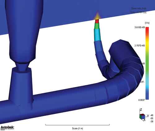
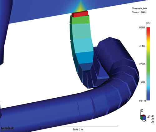
Changing the gate from a 0.060” round cashew to a 0.060” x 0.200” rectangular cashew reduces the shear rate from 3.6 times the acceptable limit to under the acceptable limit, thereby eliminating the chances of having gate blush.


In the injection molding world, everybody has an opinion about how molds should be gated – how many should be used; where should they be located; and, what size and shape should they be? Much of what is actually implemented into mold designs comes from experience, whether it is from the moldmaker, molder or material supplier. It is also heavily influenced by the aesthetic constraints of the part design (e.g., gate vestige or knit line appearance) or by any number of tooling constraints (slides, lifters, etc.).
But what happens when things go wrong at the press? What happens when you don’t get what you expected? Everyone in the injection molding industry has likely been involved in a project such as that, where something goes wrong, and then the finger-pointing begins. Wouldn’t it be nice to have a tool to predict how the gating scheme is going to affect the molded part?


The simple answer is YES, but it must be done properly, and timely. Why? Because you, as a moldmaker, are already squeezed for time when the project begins, right? If simulation takes too much time it produces project delays, which can create a lot of ill-will. Also, it goes without saying that if it is done incorrectly, the mistakes can be costly. Consequently, injection molding simulation is best left in the hands of engineers with years of experience using the software to analyze injection molds. Indeed, the real power of any simulation software lies in the ability of the engineers to get the most out of it.
How to Determine Proper Gate Locations
So, what is the right way to determine the proper gate locations? There are many things to consider, and there are often trade-offs along the way. Simulating all of the different gating possibilities provides a way to determine which one is best overall, and helps all of the stakeholders make a sound decision based on the priorities of the project.
1. Part Aesthetics
The first issue that must be addressed in deciding on the appropriate gating scheme is part aesthetics. So, as analysts, we ask the following questions:
• Are there areas of the part that must be avoided because a visible gate vestige is undesirable? Are there areas of the part where visible knit lines cannot reside?
• Are sink marks likely to occur in certain areas of the part where there are ribs or thick wall sections?
If the answer is YES to any of those questions, then those areas must be identified so that they can be considered when positioning gates. However, what may be good for knit line placement may not be good for warpage, pressure balance or fiber orientation, or any number of things.
2. Flow Balance and Flow Direction
The second question that needs to be answered is whether or not flow balance is more important than flow direction. This is particularly important for glass-fiber filled materials. The problem is that plastics do not shrink uniformly, and the orientation of fibers or molecules in the part determines the level of shrinkage variability. The molecular or fiber orientation is dictated by flow direction, which in turn is determined by gate locations.
Figure 1a,b shows a case where fiber orientation was more important than having the best pressure balance. Gating on the end of the part helped to align the fibers in one direction, which reduced the directional shrinkage variation, allowing for a flatter molded part.
3. How Far Material Must Flow
The third question that we look at to determine the best gating scheme is how far material must flow. For a very large automotive part such as a bumper fascia, this becomes very important. The distance between gates can mean the difference between having and not having appearance issues such as tiger-striping.
Flow distance also has an effect on the pressure required to fill the mold, which in turn affects the clamp force required to hold the mold shut during molding. Longer flow lengths mean higher pressures and greater clamp force requirements, particularly for thin-walled applications.
So, if your molding machine cannot handle the pressure or clamp requirements, it may be necessary to use more gates, or perhaps use a sequential valve-gate (SVG) process to get things to work. Longer flow lengths can also lead to non-uniform packing of the part, and if the part does not pack uniformly, it will not shrink uniformly. It is that shrinkage non-uniformity that causes warpage.
How to Properly Size the Gates
Once the gate locations are established, it is then important to size them properly. Why is this so important? Two reasons: 1. shearing and 2. packing.
All plastic flow in injection molding falls into the category of laminar flow, whereby the flow progresses in layers throughout the runner system, gates and into the cavity. The rate at which adjacent layers flow against each other is known as the shear rate, and is calculated in units of sec.-1 (reciprocal seconds).
Each grade of plastic resin has a shear rate limit at which its molecular chains are essentially stretched beyond their limit. Once that occurs, the material properties are degraded, which can cause appearance problems such as gate blush—or worse, decreased mechanical properties.
The average shear rate through a gate is directly proportional to the flow rate of the material and inversely proportional to the size of its orifice. That means that we can control the shear rates by controlling the flow or the gate size. The flow rate is simply controlled by the injection speed of the molding machine.
Gate size is easily changed too, but there are a couple of things to consider. It is important to determine how large of a gate vestige is acceptable. Does it need to be hidden? Is automatic de-gating necessary? How hard is it to trim?
When automatic de-gating is necessary, sub (tunnel) gates and cashew gates come immediately to mind. These gate styles typically have much higher shear rates than others because they have to remain relatively small in order to de-gate cleanly. Keeping them small also compromises their ability to pack the parts effectively.
Figure 2a,b shows a case where a small, round cashew gate was used. The shear rate predicted in that gate was nearly four times the shear rate limit of the PP material (100,000 sec.-1), which would likely result in gate blush. Changing it to a rectangular shape reduced it to an acceptable shear rate of approximately 89,000 sec.-1
Summary
As is always the case in plastics, there is a balance that must be struck among several variables, and that is most easily done by simulation, and you may not always get what you want. These are all things that we evaluate through a series of trials in the simulation software, which in the end provide the best overall solution. However remember that the solution is only as good as the engineer that performs the simulations.


Related Content

Ceramic Deburring, Deflashing Tools Take Into Consideration Difficult Materials, Operator Safety
Boride Engineered Abrasives introduces its new mold polishing equipment, the Work Finisher Tool, which is lightweight, long lasting, won’t rust and is safer and easier to use.
Read More
How To Get Buy-In from Your Team for ISO 9001
Here are four tips for getting your team on board once you’ve decided to become ISO 9001 certified.
Read More
Flowmeter Enables Accurate Water Volume Measurement, Regulation
Hasco’s flowmeter, which can be installed anywhere in the direction of flow, aids moldmakers in rapid and easy flow rate readings on injection molds.
Read More
MMT Chats: Project Engineer Applies Lean Manufacturing Principles to Growing Sustainability Role
MoldMaking Technology Editorial Director Christina Fuges catches up with MMT’s 30-Under-30 Honoree Katherine Pistorius, who has added Regional Sustainability Coordinator alongside her Project Engineer duties, which demonstrates the many paths one can take in a manufacturing career. Here she shares how this opportunity unfolded for her and what the job entails today and in the future. This episode is brought to you by ISCAR with New Ideas for Machining Intelligently.
Read MoreRead Next

Moldmaker Uses a Solution-Based Approach To Mold Flow Analysis
MoldFlow consulting firm assists mold shop as it approached a complex molding program for its customer, Cessna Aircraft Company.
Read More
How to Use Continuing Education to Remain Competitive in Moldmaking
Continued training helps moldmakers make tooling decisions and properly use the latest cutting tool to efficiently machine high-quality molds.
Read More
Are You a Moldmaker Considering 3D Printing? Consider the 3D Printing Workshop at NPE2024
Presentations will cover 3D printing for mold tooling, material innovation, product development, bridge production and full-scale, high-volume additive manufacturing.
Read More