
Using Industrial CT Scanning to Reduce Preproduction Inspection Costs
A look at the analyses that have been found to benefit major automakers, tiered suppliers and moldmakers.
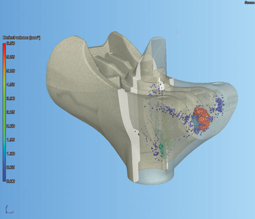
Void analysis.
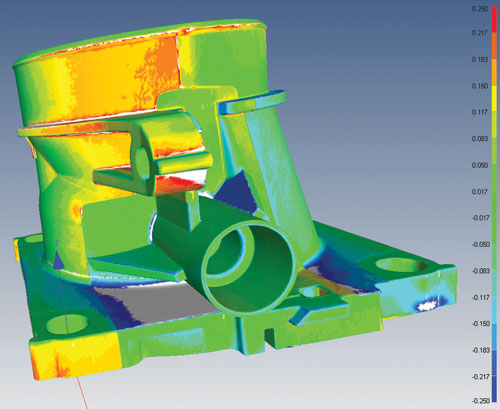
Part to CAD comparison.
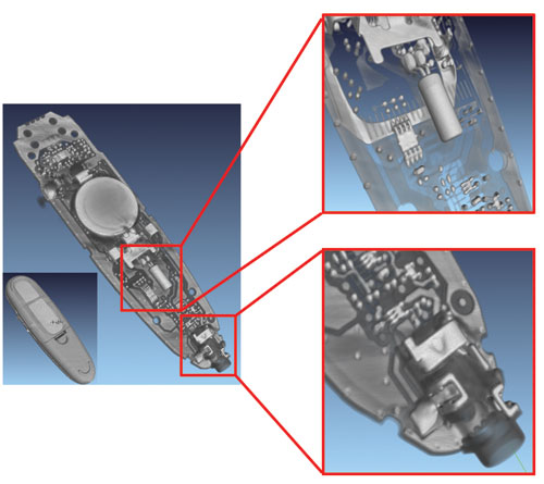
Assembly/defect analysis.


Industrial computed tomography (CT) scanning is an emerging inspection technology that has opened the door to drastically reducing preproduction inspection costs and analyzing internal failures quickly and accurately in 3-D without destructive testing. Traditionally, without destructive testing, metrology has only been performed on the exterior geometry of parts and assemblies. If a highly detailed component required inspection, the conventional method of inspection would be to fixture the part to create specified datum reference plane and go through a timely CMM touch probe inspection process or use a line of sight vision system to map exterior surfaces. Past internal
inspection methods would require taking a 2-D x-ray of the component or use destructive testing.
In its basic form industrial CT scanning is similar to a medical CAT scan, only now the CT technology is being used to scan various industrial components instead of the human body. Medical CAT scans are primarily used for visual purposes, whereas industrial CT scanning is not only for visual purposes, but metrology as well. Industrial CT scanning is a process that interlaces 2-D x-ray images to produce 3-D representations of components both internally and externally.


Because x-rays are used, delicate and fragile parts can be scanned in a free-state environment without the need for fixtures. By eliminating inspection forces or clamping procedures, the imposed inspection forces are eliminated to ensure the part is checked in its natural position. Once the scan is complete, data is reconstructed and then processed by means of a CT CAD software for part to CAD comparisons, GD&T, part to part comparisons, assembly/defect analysis, void analysis, wall thickness analysis and generation of CAD data for reverse engineering requirements. Within the CAD software, entry-level users are able to easily cross section the data, turn on/off internal assembly densities, color code density values and measure.
CT Scanning Types
Currently there are two basic types of CT scanning systems available on the market categorized based on the x-ray beam: cone beam and line beam. The cone beam systems operate by rotating the part about its vertical axis and taking a cross sectional x-ray as the part turns on a rotary table. These systems are highly accurate for analyzing parts; however, they are limited by part density and size (< 12” cubed and < 8g/cc). As industrial CT scanning is an x-ray technology, accuracy and scan resolution varies by x-ray path length and part density.
On average, the resolution of a cone beam scan ranges from 10 - 300 microns with an accuracy ranging from 3 to 25 microns. Pricing for cone beam systems typically range from $250k-$1.2m USD and vary significantly in price because of scanning resolution, maximum part size and maximum density scan values. The average scan time for cone beam systems is approximately 1-3 hours with 1 hour of post processing time for the required analysis of the CT dataset for each part.
The line beam systems operate by taking horizontal cross sectional slices as the part turns on a rotary table and then repeating this process at several predetermined vertical increments. These
systems are considered to be less accurate than the cone beam systems and primarily used for large and/or higher density parts and assemblies (<39” cubed and <16g/cc). The resolution of a line
beam scan ranges from 150 to 1000 micron with varying amounts of accuracy. Pricing for line beam systems typically range from $500k-$5m USD. Scan time for line beam systems vary from 3-24 hours and are primarily affected by the resolution required for the scan. Due to the weight of the equipment and x-ray permits required, industrial CT scanning is not a portable technology.
CT Scanning Benefits
Void Analysis: Used to determine the size and locations of porosity in thick wall plastics, injection molded parts or bonded materials without destructive testing. This type of analysis is also useful for identifying internal fibre orientation of both long and short fibres in glass-filled resins.
Wall Thickness Analysis: Used primarily for the blow mold and packaging industry to quickly and accurately measure slight changes in wall stock of complex parts without destructive testing.
Generation of CAD Data: As the 2-D x-rays are compiled into a 3-D model after scanning, internal and external data can be easily exported for reverse engineering purposes. This function is also useful for 3-D printing applications by providing data to print internal part features in conjunction with external surface geometry.
Assembly Analysis: Used to analyze internal components of an assembly meshing or snapping together. By color coding components by density values, previously hidden components
in an assembly can be easily inspected to find poor fit and function areas.
Part to Part Comparison: Used to compare two scanned parts together such as process 1 to process 2, old production parts to new capacity parts or identical parts manufactured at two different manufacturing facilities. Deviations in part variations can be easily identified to reduce costly processing times or used to validate a process.
Part to CAD Comparison: Used to compare a scanned part to CAD data. This process has showed a great deal of benefit to allow first shots to be analyzed from either local or international
tryout facilities far quicker than traditional methods. Typically at first shots, gauges are not yet manufactured and part CMM is not scheduled until 1 month after first shots.
Industrial CT scanning allows for a quick part to CAD comparison to be performed within days after the first shots. By having a part to CAD comparison at your fingertips after first shots, mold modification, tryout processing and future layout costs can be greatly reduced.
GD&T Analysis: Used in conjunction with a part to CAD comparison to analyze numerous predetermined GD&T (geometric dimensioning and tolerance) points at once to meet PPAP (production part approval process) requirements. This analysis is extremely useful and cost-effective in significantly reducing multiple cavitations part inspection costs between first shots and production. Once the initial GD&T layout plan has been developed for the CT dataset, all GD&T points can be quickly transferred and applied to subsequently scanned parts.
Specific to the plastics industry, the aforementioned analyses have been found to benefit major automakers, tiered suppliers and moldmakers.


Related Content

Precision Welding Services Offer Rapid Turnaround Mold Repair and Reduced Molder Downtime
X-Cell Tool & Mold relies on outsourced, high-quality welding repairs from Lewis-Bawol Welding to ensure its customers' molds are back in production quickly and affordably.
Read More
Portable Low-Heat, Non-Arcing Resistance Welder for Mold Repair
Rocklin’s user-friendly MoldMender Micro Welder delivers simple and cost-effective localized repair in-house with precision and versatility, enhancing mold and die durability and reducing disassembly and downtime.
Read More

Predictive Manufacturing Moves Mold Builder into Advanced Medical Component Manufacturing
From a hot rod hobby, medical molds and shop performance to technology extremes, key relationships and a growth strategy, it’s obvious details matter at Eden Tool.
Read MoreRead Next

Reasons to Use Fiber Lasers for Mold Cleaning
Fiber lasers offer a simplicity, speed, control and portability, minimizing mold cleaning risks.
Read More
How to Use Strategic Planning Tools, Data to Manage the Human Side of Business
Q&A with Marion Wells, MMT EAB member and founder of Human Asset Management.
Read More
How to Use Continuing Education to Remain Competitive in Moldmaking
Continued training helps moldmakers make tooling decisions and properly use the latest cutting tool to efficiently machine high-quality molds.
Read More