Toolroom Perspective on Micro Molding
Design for manufacturing, or more specifically design for micro molding is critical to this mold manufacturing niche as it presents unique challenges and impacts the tool build.


An interesting release came across my inbox recently from Accumold's new tooling team leader, Jeremy St. Peter. If you are not familiar with Accumold, let me give you a brief snapshot before sharing Jeremy’s insight on design for micro molding.
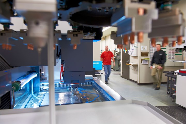
Accumold, based in Ankeny, Iowa, has 30 years of experience working with OEMs that require complex micro-sized electronic components and connectors. The company has grown to a 130,000- square-foot facility designed for assurance of supply, employs over 350 workers and is a net exporter shipping worldwide every day from its U.S. facility that runs 24 hours a day, seven days a week.


With that being said, this article by Jeremy digs deep into the importance of Design for Manufacturing (DfM) more specifically, Design for Micro Molding (DfMM), as this niche presents unique challenges and DfMM has a massive impact on the tool build.
Here are Jeremy’s words:
Success in micro molding is genuinely a result of multi-disciplinary expertise. Tooling is only one of several critical areas where your chosen micro molder must show experience and knowledge. The best micro molders are indeed vertically integrated, and teams from design, tooling, molding, validation, and automated assembly must work collaboratively to optimize product development outcomes on behalf of customers.
It is also essential that individuals within specific departments have a rounded view of their area of focus. For example, my career in toolmaking started at a die shop, which I left after a year to come to Accumold, where I have worked for 17 years.
At Accumold, I began by applying my die experience to the development and maintenance of dies and molds in lead frame systems. While working with these systems, I gained some automation experience, and I also began to focus on mold maintenance and repair.
With some cross-training, I learned to program and cut electrodes that were used on all my repairs, which led me to program and cut electrodes full time for about two years before returning to the bench to build micro molds. Exposure to many different business areas has given me a unique perspective, which has proven valuable when working with DfMM and tool fabrication.
Micro Tooling Considerations
The necessity to focus metrology and validation on the micro tool is in large part due to the specific contingencies that exist in the area of micro moldmaking, and how these contingencies can affect design parameters and ultimately the integrity of the finished tool and finished part. Of special interest are issues concerning gating, ejection, mold splits, and direction of pull.
Ejection & Gating. Often when a part gets smaller, the first thing that gets eliminated or ignored in the design is any consideration of ejection or gating. However, the engineering team understands that a part cannot be made without either of these. Keeping gating and ejection in mind during part design can optimize the DfMM and tool build process. For example, having a small ejector pin on a thin and deep feature can make burning a start hole difficult or impossible. Also, gating in a thin area when there are other thick areas can cause non-fill and sink. When planning for gating and ejection, we must anticipate some gate vestige or flash, so in an assembly of parts, this may have to be planned for. When deciding mold splits, it can turn a simple tool build into a very complex one, or it can turn a tool that was going to be very difficult to run into a tool that runs exceptionally well.
Split Lines. When looking at split lines, customers often prefer not to have them in certain areas due to flash. However, changing from an ideal split line from the tool perspective can cause unforeseen consequences to the tool build.
A project comes to mind where the preferred split from the tool making perspective would have been a saddle shutoff, but due to flash concerns, the shutoff was placed on a slide to make the flash direction perpendicular rather than parallel. The slide created some cosmetic areas, so this caused us to shut off on the cosmetic surface. The unforeseen consequence of this was that there was more flash than anticipated in the windows in the preferred flash direction, and there was some mismatch between the slide and the rest of the cavity. Doing a saddle shutoff, in this case, would have put all the cosmetic surfaces on one side of the tool, and while the potential for flash would still have existed, the shutoff would have been in the direction of the clamp rather than on a slide pull. This would also have eliminated a split line on the cosmetic surface and improved the overall part appearance.
A consistent view of DfMM will not only improve the reliability of the mold but also reduce the time it takes to manufacture.
A slide with a large surface area presents the possibility for injection pressure to flex the mold, so if you can have a shutoff in the direction of pull, it is always a more robust shutoff. The clamp direction holds a shutoff together as a direct result of clamp tonnage, while alternatively, a slide is a factor of the tonnage reduced by the heel angle and strength surrounding mold steel.
Feature Size. Another thing that can influence tool build is feature size. I can think of several times where the part tolerance was used to increase the thickness of an area to fill. When working with micro molded parts, it is best to remember that although it may sound like a small change, it may represent a large percentage of the feature size. For example, if you have a part with a .004" (0.1 mm) wall thickness, changing that wall thickness by .0005" (0.013 mm) is a 12% change and may mean the difference between filling the area reliably or not.
When it comes to creating electrodes to burn the cavity, the amount and difficulty can be significantly affected by the part's design. For example, if there is a square counterbore with sharp corners, we may have to use four different electrodes to create this feature; If the part had radii added at the corners, this might be possible using only one electrode. The depth of the feature is something to think about when adding radii as well. An extremely small radius on a deep feature may not be possible to cut, so if the radius can be increased slightly, it can change the difficulty of the electrode significantly.
When it comes to ensuring a part will release from the cavity, an essential factor — especially when dealing with very small features — is draft. Often with small parts, draft is an oversight because it will be such a small amount. Again, it is essential to look at percentages instead of actual sizes. Adding 0.5 degrees draft on a 0.10" (0.25 mm) tall feature may not sound important, but that can add 0.0009" (0.023 mm) of draft, so on a thin 0.010" (0.25 mm) feature, it is almost 10% of the feature's thickness.
Assembly. Consideration of assembly of several parts is also important in terms of final product optimization and ease of tool build. When building a mold, it can be easy to believe you are in a situation where everything must be machined precisely to size. I prefer, however, to hedge my bets and add clearance when possible to minimize the number of areas that need to be accurate. Adding clearance allows the choice of a less accurate method to manufacture for certain parts, leaving the accurate machining to areas where it is needed, saving time. Clearance on the parts being molded can be approached the same way. This also applies to the part tolerance on a plastic part.
A consistent view of DfMM will not only improve the reliability of the mold but also reduce the time it takes to manufacture.


Related Content

OEE Monitoring System Addresses Root Cause of Machine Downtime
Unique sensor and patent-pending algorithm of the Amper machine analytics system measures current draw to quickly and inexpensively inform manufacturers which machines are down and why.
Read More
What is Scientific Maintenance? Part 2
Part two of this three-part series explains specific data that toolrooms must collect, analyze and use to truly advance to a scientific maintenance culture where you can measure real data and drive decisions.
Read More
How to Select a Mold Temperature Controller
White paper shares how cooling channel analysis, which collects maximum pressure drop, total flow rate and heat dissipation, eases the performance evaluation of mold temperature controllers.
Read More
MoldMaking Technology's Most-Viewed Content 2022: Products
MMT shares the five top-viewed technologies, equipment and services of 2022 in each Engineer, Build, Maintain and Manage tenet based on Google Analytics.
Read MoreRead Next

Are You a Moldmaker Considering 3D Printing? Consider the 3D Printing Workshop at NPE2024
Presentations will cover 3D printing for mold tooling, material innovation, product development, bridge production and full-scale, high-volume additive manufacturing.
Read More
How to Use Continuing Education to Remain Competitive in Moldmaking
Continued training helps moldmakers make tooling decisions and properly use the latest cutting tool to efficiently machine high-quality molds.
Read More
How to Use Strategic Planning Tools, Data to Manage the Human Side of Business
Q&A with Marion Wells, MMT EAB member and founder of Human Asset Management.
Read More