Thermography: From Benchmark to Diagnostic Tool
It all starts with a part. There’s a problem. Whether it’s a cosmetic appearance issue, or perhaps a dimension out of tolerance it’s relatively easy to identify if there’s a problem. However, a diagnosis based on that same visual observation will also likely not identify the root cause.
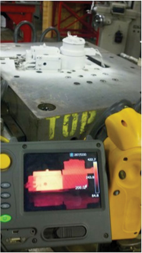
Figure 1 Thermography gives its users the means to communicate critical application-related data to both technical and non-technical people in a position of authority that need good data in order to make good, sound business decisions.
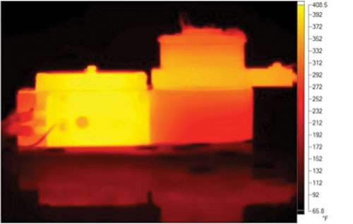
Figure 2 Thermographic analysis revealed plugged water cooling lines, and manifold design flaws, which resulted in non-uniform heating.
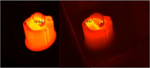
Figure 3 A non-uniform wall detected by thermography was identified as the root cause of production defects on these medical parts.
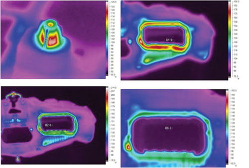
Figure 4 The instrument panel top section had thick sections around the air bag opening and under the lifters. Thermographic analysis allowed these to be readily identified early and then corrected.
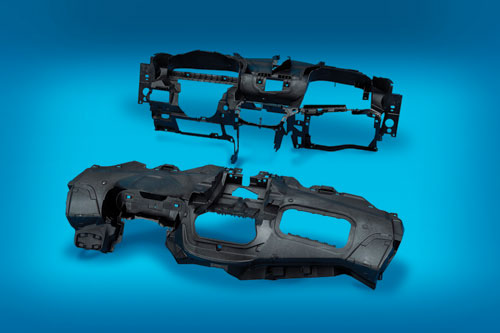
Figure 5 This finished instrument panel for the 2012 Ford Escape won the Grand Award at the SPE Automotive Innovation Awards held in November, 2011.
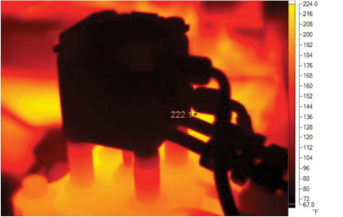
Figure 6 Thermographic analysis is useful in failure prediction. In this case the analysis tested the effect of a cooling water system failure on the cylinders.
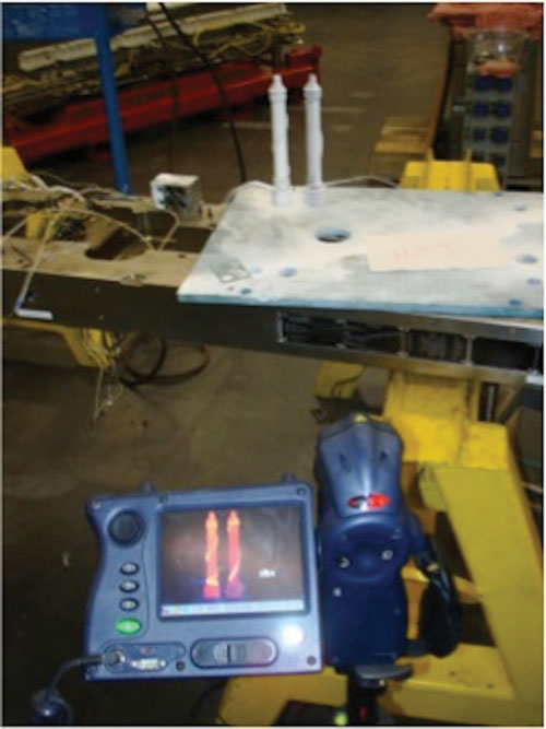
Figure 7 A thermal analysis was able to determine that material degradation was not shear related, but rather heat induction related.


There could be other processing issues, such as lengthening cycle times, hot spots or increased injection pressures. Again, traditional visual observations may not help to identify the root cause of the problem.
Perhaps it’s time to take a look with a fresh lens—from a thermal imaging camera (see Figure 1). Thermography is the recording of infrared energy and converting it into a visible light image to be used for a variety of applications. Thermography is a tool that when used in combination with physical temperature measurements and common sense offers a glimpse into a previously hidden world. It allows you to look to your part as a key data source to analyze and troubleshoot your process, manifold, mold construction and mold cooling system. If you have the thermal profile of a part as a baseline or point of reference, in the future when a problem comes up you can refer to this baseline information to identify what’s different.
For moldmakers and molders there are two major practical uses for thermography and following is case study data to illustrate areas in which thermography is useful.
The Discipline of a Thermal Audit
Thermography is a useful tool when conducting tooling audits. It’s especially useful when auditing transfer/takeover tools. Many of these tools arrive at a molder’s door with either limited documentation, or none whatsoever.
Thermography’s value in troubleshooting is complemented by closing the gap in communication between technical and non-technical people. Some of the people are in a position of authority and they need useful data in order to make well-informed business decisions.
The performance of the mold’s cooling system is what comes to mind most readily for molders when it comes to thermal analysis. Seven-plus years of thermography use has discovered mold cooling problems to be a frequent occurrence, and one that is easily uncovered whenever a thermal audit is conducted. From clogged cooling channels, to missing channels altogether, thermography helps you to readily identify these types of issues in tooling.
The hot runner manifold system itself, along with the injection mold can be studied, with problem areas quickly identified (especially in nozzle tip areas). This then allows proper performance benchmark numbers to be established and documented.
Thermography allows excellent views of the piece part upon ejection from the mold, so that benchmarks can be established. Finally, special considerations—such as the need for beryllium-free high strength copper alloy or aluminum inserts—can all be documented with performance benchmarks established in advance prior to actual production use.
Troubleshooting Case Study #1: Medical Shelving Unit
There are two main issues with the part in Figure 2. First, the molder thinks they were experiencing degradation of a silicone additive for lubricity, which was showing up randomly in the molded part. The current configuration is causing excessive scrap rates that are not controllable with any degree of consistency. In addition, cycle time, although targeted at 55 seconds is running at 70 seconds. In fact even when new, the tool never ran at the targeted cycle time.
A thermal tooling audit was executed and it validated three points of concern. First, the injection mold was built in 1984. Were the water lines plugged? Yes, almost completely. Second, it was discovered that the manifold system was designed wrong. The components were failing due to age, which compounded the problem. Further study revealed that the manifold system’s design failures are responsible for the non-uniform heat.
Thermographic analysis also revealed the wattage-to-mass ratio on one end of the manifold was too great and almost entirely lacking on the other side.
As of the time this article was being prepared, evaluation and repairs are underway. Based on prior experience and successes, it is certain the cycle time can be brought down to the 60-second range and eliminate the degrading silicone issue.
There is still a remote chance the master batch is causing at least some of the performance issues, and work is underway directly with a chemist and the injection molder to evaluate this possibility.
Troubleshooting Case Study #2: Uniform Wall Stock Detection
Production defects, a stringing gate point and longer than quoted cycle times were seen in polycarbonate parts molded for a medical applications (see Figure 3). The root cause was detected and identified through the use of thermography. In this application, a non-uniform wall was the largest influence. The 3-D part data did not reflect the actual molded parts so Mold-Flow would have not predicted the same as the actual situation either.
Troubleshooting Case Study #3: Uniform Wall Stock Detection in a MuCell Application
The instrument panel top section (see Figures 4, 5) had thick sections around the air bag opening and especially under the lifters. These thick sections were identified early with the use of thermal imaging and corrected before the tool was 100 percent finalized.
Troubleshooting Case Study #4: H2O Cooled Hydraulic Cylinder Failure Prediction
For this application (Figure 6) the manifold starts at 212ºF in soft start mode. The temperature is then increased to 560ºF (heaters run in excess of 650ºF to achieve this). This is normal. The cylinder is water cooled to prevent damage to the seals inside. The water was turned off and the cooling cycle was documented. Plus it was discovered that even if the water is turned off while the power is on these specific cylinders will never reach a temperature that would allow for damage to the seals. This was tested in 30-minute cycles.
Troubleshooting Case Study #5: Solar Panel End Cap Production
For this application, the molder was experiencing degradation in the material causing excessive and expensive downtime and scrap. In fact, the problems were so bad that the molder was forced to purchase a second $100K+ hot half from the original OEM to keep downtime to a minimum, as they were required to spend thousands of dollars along with countless manhours every two weeks to clean out the existing manifold.
A thermal analysis was executed and it was found there were three major points of concern: 1. the material had flame retardant inside and no details were available for review; 2. the nozzle heater profiles were wrong; and, 3. the internal flow paths in the manifold had sharp edges causing excessive shear, which contributed to the degrading of the resin.
Major Issue #1: The material used in the application is shear-dependent. A contoured flow path manifold like the one used in this application minimizes shear in theory. Bore sizing should be done to promote shear while considering the injection pressure relative to press capabilities (Figure 7).
Analysis led to the belief that the degrading was not shear related, but rather heat induction related. There was too much wattage in a small area, which affected the material as it sat during the part cycle. The degradation, combined with the presence of the flame retardant attacked the melt flow bore (nozzle steel) in the area that was elevated in temperature. As a consequence, the degraded material started to adhere in small amounts. As this cycle continued the buildup increased and restricted the flow path while increasing injection pressure. This buildup also acted as an insulator. When it reached a certain thickness it was no longer possible to effectively heat the material in that area.
Major Issue #2: The profile at the nozzle contact areas in the manifold contributed to the degrading of material in the nozzle flow path. When assembled in the mold the transfer of heat should be more efficient at contact due to thermal expansion pressure forcing full contact. It is known that the profile is influenced by the mold assembly. The repeatable issues with specific nozzles in the existing tool need to be looked at again and a root cause determined.
Major issue #3: Initially, 420-watt heaters were supplied by PSG (). However, as a result of the actual manifold heat profile the 420-watt heater added to the problem, which accelerated the effect of degraded material in the nozzle flow path. The 420-watt heater was replaced with a 390-watt heater with 1.5 wraps on the wire exit end of the nozzle.
The image sequence is the 390-watt heater shown during a normal heat cycle. You will note there is no thermal load taking away heat at the tip area or the head area. When the nozzle is installed into the mold, the tip area will cool very rapidly, having the thermocouple call for power. As a result, more heat is put into the mass than is needed. This is why the wattage and the linear mm (inches) of heater to nozzle contact was reduced. This is a normal nozzle heat profile challenge complicated by the manifold heat profile.


Related Content

The Benefits of Hand Scraping
Accuracy and flatness are two benefits of hand scraping that help improve machine loop stiffness, workpiece surface finish and component geometry.
Read More
Fundamentals of Designing the Optimal Cooling System
The right mold components can help improve mold cooling and thereby produce higher-quality parts.
Read More
Solving Mold Alignment Problems with the Right Alignment Lock
Correct alignment lock selection can reduce maintenance costs and molding downtime, as well as increase part quality over the mold’s entire life.
Read More
Laser Welding Versus Micro Welding
The latest battle in finely detailed restoration/repair of mold materials.
Read MoreRead Next

Using Digital Thermography in Mold Manufacture
Digital thermography is an effective tool for bringing solutions to your customers.
Read More
Are You a Moldmaker Considering 3D Printing? Consider the 3D Printing Workshop at NPE2024
Presentations will cover 3D printing for mold tooling, material innovation, product development, bridge production and full-scale, high-volume additive manufacturing.
Read More
How to Use Strategic Planning Tools, Data to Manage the Human Side of Business
Q&A with Marion Wells, MMT EAB member and founder of Human Asset Management.
Read More