
The Moldmaker’s Role in Controlling the Molding Process
How the toolmaker/mold designer can make the best choices when it comes to in-mold cavity sensing and control; how to do a good installation; basic functionality of the sensors; and, post installation care.


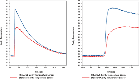
Figure 3. Rapid response and high signal amplitude are essential for the cavity temperature sensors you choose for your control systems. The chart shows a typical course of the cavity temperature during an injection cycle. In the figure on the right, the abscissa is zoomed in.
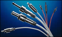
Figure 2. New series of miniature cavity pressure sensors and miniature cavity temperature sensors with 0.6 and 1.0mm front diameters.
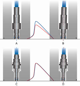
Figure 1. A side load or force shunt acts as an interference when the sensor tip touches the bore. The measuring principle avoids this measuring error. Standard sensor (a) optimally installed and (b) with side load and sensitivity loss; sensor (c) optimally installed and (d) side load has no effect on sensor response. Figures courtesy of Priamus.
The basis for making consistent parts for your customers is simply identifying where the physics and chemistry of plastics processing come together—inside of the mold cavity. It is in the cavity where the plastic changes from a liquid to a solid. In other words, this is where the PVT (Pressure-Volume-Temperature) properties of the plastic occur. To make consistent parts, the PVT relationships from cavity to cavity must be consistent.
The “P” in the equation is cavity pressure. For decades, it has been well known that cavity pressure is the best and most appropriate signal for process optimization. However, cavity pressure is only part of the story. Coupled with the “T” in the equation—or cavity temperature—the location of the melt front is directly ascertained; any changes in material viscosity are precisely known.


How to Use PVT Technology
There are two important considerations in utilizing PVT technology: sensor placement and sensor type.
Sensor Placement
The standard rule of thumb for cavity temperature sensors being used to identify and balance melt fronts is to place them at a point at which the part is approximately 85 to 90 percent filled. This will allow effective switchover signal while providing enough time for the molding machine to react without overfilling the cavity or flashing.
Cavity pressure sensors, on the other hand, need to yield the maximum amount of information and the strongest signal. For this reason, the sensor should be located in the first 30 percent of the fill. Placement beside a detail, where a reduction in wall thickness or at locations where major changes in geometry are taking place should be avoided if possible. Placement on a nominal thickness wall usually in the first third of the flow path after the gate is generally the best scenario for gaining the strongest and the most accurate signal and the accompanying picture that it will provide.
Note: Both types of sensors can be placed in other locations for informational purposes. The placement of sensors, as previously suggested, is the most practical and effective method for current injection molding technology available to the molding industry.
Sensor Type
In general terms, when it comes to pressure sensing in the mold cavity there are two types of sensors to consider: direct and indirect. Indirect sensors are typically placed under an ejector pin or dummy pin that is in an appropriate location in the cavity. Many times the signal achieved in this manner is not maximized due to using already existing ejector pin locations. There is an added effect of a moving link in the data chain that can be adversely affected by build up in the mold, any unevenness in the ejector system, or normal wear and tear on mechanical parts.
The use of flush-mounted cavity pressure sensors placed directly in the mold cavity where melt contact is made, provide the most reliable measurement. Sensors under pins are effective and easier to install upfront, but are in fact another link in the chain that can go wrong. When designing a mold you always want to avoid moving parts if you have a choice, mostly for maintenance reasons. The same consideration should be taken when making the decision to instrument a mold.
Piezoelectric cavity pressure sensors, which make direct contact with the melt flow are a good choice because their performance is robust even at extreme pressures and temperatures, as well as repeatable for a variety of measuring ranges. The high frequency response ensures that the process information is captured the most effectively.
Sensor installation is critical. If the sensor tip touches the bore wall, a side load or force shunt effect, can occur. This results in a loss of signal or sensitivity. This influence increases as sensor size decreases because the required tolerances are more difficult to maintain for very small bores.
There are sensors available today that have been encased in hardened sleeves to eliminate any side force issues in the event of a less than perfect installation (see Figure 1).
The actual cavity pressure sensor should be securely installed in a housing that has been made to very narrow tolerances. The sensor should then be calibrated in the “installed” condition and the sensitivity of the sensor stored as a code inside of the sensor itself. When the sensor is installed in the mold cavity, side load effects will be eliminated by the protective housing and measuring signals will be reproducible. The connected electronics read the sensor sensitivity and automatically adjust the measuring range for the best signal resolution possible.
Cavity temperature sensors are the N type. They too make direct contact with the melt and also require a straight bore and solid mounting. They are very small (0.6mm-1.0mm front diameter) so that response time is very rapid (2 to 3 msec) (see Figures 2 and 3). The sensors are dynamically calibrated to guarantee signal amplitude and response time lie within the required tolerances.
The cavity temperatures sensor located near the end of the flow path initially measures mold surface temperature and then the melt contact temperature, when the plastic touches the sensor. This signal, combined with the corresponding electronics, can be used in real-time closed-loop control systems for automatic switchover to holding pressure.
In hot runner or gate valve tooling much improved cavity-to-cavity balance can be achieved as the control system will not switch over to holding until all cavities are volumetrically full. Temperature sensors can detect changes in viscosity faster and more sensitively than the typical pressure sensing setup, and therefore can be quite an advantage in reducing mold damage and keeping parts in tolerance.
Other control applications based upon melt front detection—such as sequential molding, LSR, gas-assist, coining, closing of venting cores as well as automatic balancing of hot runner multi-cavity molds—are possible only with the correct cavity temperature solution.
Among other considerations to be made with both types of sensors will be the ability to machine sensor tips (contourable), wire configuration and length, connection type, sensitivity, durability and mounting recommendations.
All of the installation information needed is available; however, the designer/toolmaker would be wise to review all aspects with a technical representative from the sensor supplier. Wiring is critical; connections must be clean and properly insulated. Like any new technology, if your moldmaker is not familiar with sensors it is of utmost importance that they obtain the maximum amount of information available prior to attempting installation.
Pre-Post Installation Care
Having knowledge of all of the above, the mold designer/builder can make arrangements within the tool design so as not to interfere with water, air and ejection when laying out the mold. The sensors are relatively small, but must be placed where they can be solidly backed up or directly secured with mounting nuts. Access needs to be provided for maintenance. Choosing the correct setup can make a big difference in the time spent on maintaining the system over the life of the mold.
Surface contact sensors should be very low maintenance as the surface needs to be kept clean as is your typical mold surface so no additional work is involved. The connections need to be capped and kept clean when disconnected. Caps are provided by the supplier and this becomes a matter of discipline with the molding personnel for utilization. Indirect contact systems on the other hand require regular cleaning of the moving parts to avoid build up of gasses and plastic.
Summary
Cavity pressure sensing technology is not new to the industry, but the addition of cavity temperature sensing is rather young. This added ability has virtually given the molder another set of eyes in the cavity. Where we were limited to looking at only one of the three “PVT” variables past, now we can completely define the molding process in real-time based upon plastic related information.
Having the ability to see in real time how adjustments to any of these variables reflect on the others is a huge advantage to maintaining part integrity as well as providing a much faster learning curve for processing personnel. Closing the loop and responding to changing viscosity is a huge step in the direction of getting complete control of the molding process. The molding industry has only just begun to scratch the surface of the added possibilities that this technology will provide.


Related Content

MMT Chats: Acquisition Trends and Lessons for Mold Builders
Jim Berklas is a former full-time M&A lawyer for several of the largest private equity firms in the country and has 25 years of M&A experience and 200 closed transaction. Today, he is founder and M&A Leader with Augmented Industry Services. He joins me for this MMT Chat on mergers and acquisitions trends and strategies within in the mold manufacturing industry. This episode is brought to you by ISCAR with New Ideas for Machining Intelligently.
Read More
OEE Monitoring System Addresses Root Cause of Machine Downtime
Unique sensor and patent-pending algorithm of the Amper machine analytics system measures current draw to quickly and inexpensively inform manufacturers which machines are down and why.
Read More
The Trifecta of Competitive Toolmaking
Process, technology and people form the foundations of the business philosophy in place at Eifel Mold & Engineering.
Read More
Editorial Guidelines: Editorial Advisory Board
The Editorial Advisory Board of MoldMaking Technology is made up of authorities with expertise within their respective business, industry, technology and profession. Their role is to advise on timely issues, trends, advances in the field, offer editorial thought and direction, review and comment on specific articles and generally act as a sounding board and a conscience for the publication.
Read MoreRead Next

Improving Shear-Induced Imbalance in Hot Runner Systems
Even melt distribution and balanced filling to and across all cavities while avoiding restrictive mixers is possible with hot runner manifold construction that incorporates a melt rotation design.
Read More
New Technology Helps Users Accurately Design Molds
VISI-Flow software helps mold shop determine optimum mold specifications.
Read More
Achieving Cavity Balance: Another Factor for Success
A look at good and bad cavity layouts and runner designs.
Read More