The Misunderstood Cutter Path
Normal vectors are not always the best choice for milling complex mold surfaces.
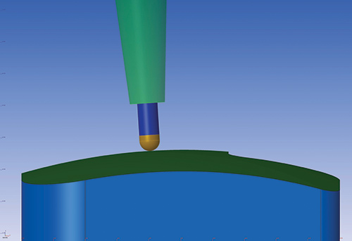
Fig. 1 - In this illustration, the tool axis is normal to the face of the part being milled. Figures courtesy of Vero Software.
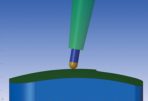
Fig. 2 - Here, the tool axis is tipped from the normal position to avoid milling with the very tip of the tool.
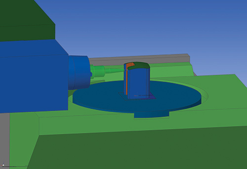
Fig. 3 - It is not usually practical to mill normal to the surface when machining steep walls or pockets.
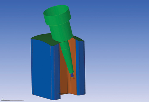
Fig. 4 - This tool is normal to the face of the part in one axis, but it can still cause collisions.
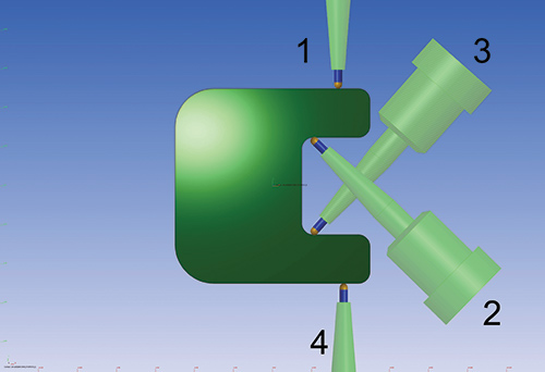
Fig. 5 - This illustration shows how the tool moves from position 1 to 2 to 3 to 4 in order to remain as normal to the surface as possible and still remain collision-free. This method causes large reversals of the rotating axis (or back and forth movements).
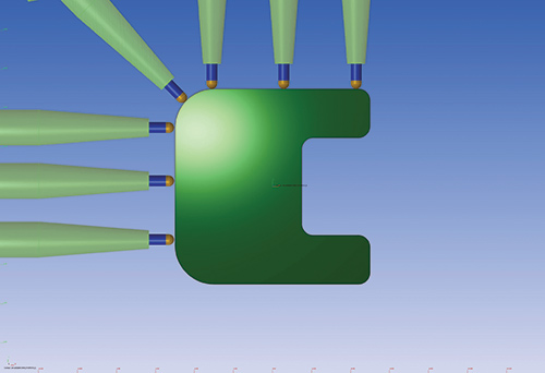
Fig. 6 - Here, the rotating axis stops at each straight section and then starts rotating again.
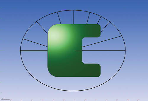
Fig. 7 - With an input curve, the axis can stay in motion and reduce reversal movements.


Five-axis machining is attractive to moldmakers because it can produce improved surface finishes, and it can be more effective for milling steep areas and pockets in molds. Achieving these goals requires an understanding of which types of cutting paths are appropriate for such applications.
A common five-axis cutter path is normal to the faces of the part. While, in milling, this often provides reduced tool deflections and vibrations, it is not always practical to machine this way on the steep areas of many molds, simply because of machine kinematics. Here, we’ll examine appropriate applications and methods for using normal vectors for five-axis milling in moldmaking.


Force Effect
Cutting tools experience force on both the tool shank and on the cutting edges. The forces on the shank are both axial, in line with the tool axis, which compresses the tool, and lateral, sideways to the tool, which causes the tool to bend. When the tool finishes normal to the faces that are being cut, the ratio of axial forces to lateral forces is higher towards the axial forces, allowing more of the cutter forces to be transferred through the tool axis. As the tool contact point moves from a normal position to sideways, the amount of lateral force increases. This induces a slight tool deflection, and since the tool is also rotating, tool vibration can occur. Milling normal means less tool deflection and reduced tool vibration, which yields better and more accurate finishes (see Figure 1).
For practical purposes and programming ease, a ballnose tool typically is used for many five-axis finish cuts, because the tool can rotate around the center point of the ball using five-axis programming and still maintain the same contact point with the part. Tool diameter is used to calculate the surface feet per minute (sfm). As the contact point moves closer and closer to the tip of the ball, the effective cutting diameter continues to shrink and this cutting speed measurement starts to approach zero. When this happens while milling normal to the surface, it can be difficult to utilize feed rates and spindle speeds recommended by the tool manufacturers. This, combined with difficulty in creating a quality cutting edge at the very tip of the tool, can contribute to a poor surface finish.
To work around this difficulty, many programmers will insert a lead angle into the cutting program. Instead of cutting perfectly normal or perpendicular to the geometry, the tool is tilted forward to cut at a set angle. This moves the actual contact point away from the cutter tip to another portion of the tool, which then allows for cutting speed calculations that are not near zero when milling away from the tip. Using a lead angle does introduce some lateral forces, but the majority of forces are still axial and directed along the tool axis, resulting in no deflection or vibration. Lead angle five-axis machining therefore is often preferred when milling a part’s flat and/or shallow, sloped areas (see Figure 2). However, actual milling machine kinematics may sometimes not support lead angle machining.
Alternatives for Impractical Applications
When milling relatively steep areas, such as pockets or inserts, it is not practical to mill truly normal to the surfaces, as the rotations necessary to accomplish this task often are outside the limits of the machine. It also requires the part to be mounted at an impractical height to ensure the head does not collide with the table (see Figure 3).
An alternative to milling normal for steep areas is using a constant rotational axis (often the C axis of a rotating table), which entails the part being mounted to a table that can spin continuously or the head of the mill spinning around the part continuously. In this case, the tool and spindle are inclined at an angle necessary to reach the deep areas while the part is rotated during the milling process. This is not unlike how a part is rotated on a lathe. The head inclination is often to the A or B axis, depending on the mill configuration.
In this scenario, many CAM systems keep the rotating axis normal to the faces being milled, locking the inclination to avoid head collisions. This method can work in many situations, but it can be problematic when milling a part’s concave regions, where remaining normal in the one axis would cause collisions between the part and machine spindle (see Figure 4). Here, automatic collision avoidance is the preferred method of calculating the CAM cutter path on the part. This involves programming software that automatically rotates the tool, holder and spindle to avoid collisions with the part during milling. However, some important programming options will work better than others for this type of milling.
Many five-axis CAM algorithms modify the constant rotational axis to avoid a collision, then rotate the axis back to a normal orientation. While this avoids collisions, it may not be optimal when you also consider a machine’s dynamics. For example, performing holder and spindle avoidance may introduce an excessive amount of directional changes in the mill’s rotational axis. That is, the rotation may switch from clockwise to counter-clockwise and back several times during the toolholder avoidance stage as the algorithm attempts to maintain the rotational component of the tool normal to the geometry being milled. This is similar to what occurs in three-axis operations, when every time the direction of a machine axis is reversed, it affects the milling machine performance and surface finish in that location (see Figure 5). Instead, it can be beneficial to program the cutter path with only those transitions necessary to avoid collisions. This allows fewer reversals in axis direction and places higher importance on smooth transitions than on forcing the tool to be normal in that axis.
Smooth Milling Options
Milling machines benefit from smooth movements, so the rotational axis should remain in motion rather than repeatedly starting and stopping. Imagine five-axis milling of a cube with rounded corners. On the straight portions of the cube, the part does not need to be rotated. It can be milled with just a simple, linear, three-axis movement. Yet, as the cutter approaches the corners to be rounded, the part rotates simultaneously with the linear axes. The changes in machine vibration as the axis starts and stops can often affect the surface finish of the part (see Figure 6).
While it is theoretically possible to manually program and set the rotational value for a part, molds include complex, freeform shapes that require millions of CAM-programmed points. A fully manual method for controlling the rotational axis for complex mold shapes is impractical. CAM software programs specifically designed for moldmaking incorporate different methods for handling the issues that arise from axis reversals and stoppages. One example is a semi-automated method using a specific milling algorithm that analyzes the part, avoids collisions and looks far enough ahead to smooth out transitions in the calculated cutter paths. Another method incorporates user-created wireframe shapes that help guide and direct the mill’s continual rotational axis. A curve, for example, can be used to determine the general direction of a tool tilt and provide input on how the continual axis rotates (see Figure 7).
Input drive geometry enables the axis to remain in continuous motion without a large number of stoppages or axis reversals. This works by allowing the CAM algorithm to use the drive geometry as a guide for the part rotations, as long as there are no imminent tool collisions. If the input curve is continuous and smooth, the CAM algorithm will use that as a model for its output rotations. Smoother rotations with fewer changes in direction will result in faster performance and better finishes.
Even when methods such as these are employed, complexities associated with molds today demand that the algorithm of the CAM system places the most importance on toolholder and spindle avoidance, and secondary importance on the input drive curve. Although there may be automatic algorithms for five-axis machining that allow toolholder and spindle avoidance to mill deeper with shorter tools, axis control is still an important consideration to make a five-axis machine run smoothly and efficiently.
WorkNC by Vero Software


Related Content

Mold Innovations Power Unique Auto Lighting Elements on Hummer EVs
Diamond machining, electroforming of micro-optical inserts and modified latch-lock system help injection molds produce unique forward lighting elements.
Read More
MoldMaking Technology's Most-Viewed Content 2022: Products
MMT shares the five top-viewed technologies, equipment and services of 2022 in each Engineer, Build, Maintain and Manage tenet based on Google Analytics.
Read More
How to Manage Wall Thickness Changes in Your Mold Design
To ensure even filling and cooling, consider wall section transitions, corners and fillets, ribs and bosses, lip and rim designs and CAE flow simulation software.
Read More
New Innovations in Mold Design, Milling Cutters, 3D Scanning
MoldMaking Technology compiles a number of digital-only products from the past month, including mold design software, laser metrology 3D scanners, milling cutters and more.
Read MoreRead Next

Four Steps to CAM Selection
Considerations when choosing the right CAM system solution for your mold build operation.
Read More
Are You a Moldmaker Considering 3D Printing? Consider the 3D Printing Workshop at NPE2024
Presentations will cover 3D printing for mold tooling, material innovation, product development, bridge production and full-scale, high-volume additive manufacturing.
Read More
How to Use Strategic Planning Tools, Data to Manage the Human Side of Business
Q&A with Marion Wells, MMT EAB member and founder of Human Asset Management.
Read More