
The Key to Controlling Your Machining Process
Controlling heat is the most important factor in high-speed and hard metal machining.


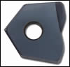
High feed insert. Images courtesy of Millstar and Commercial Tool and Die.
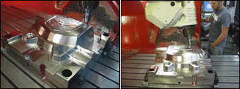
Mold that was machined using high-speed machining (P20 material).

P20 material being machined with a high feed insert tool.
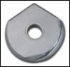
3-D helical grind on a ball insert.
3-D helical grind on a ball insert.
Over the past decade high velocity and hardened metal machining has become fairly commonplace in the die/mold, aerospace and medical component industries. The machining process has not changed much, but the cutting tools required have changed dramatically.


Tooling Requirements
Efficient high-speed and hard machining of molds, dies and other components requires tooling that can take the heat of the higher surface speed. The tooling also must have the edge preparation to hold up to the forces and abrasion of higher speed milling.
Coatings
The most important thing to take the heat is in the coatings. TiAlN (AlTiN)-coated tools are best for steels over 40 HRc or running over 800 sfm. There are many different variations of each of these coatings since there are many different companies that coat tools. Trial and error is the only way to decide which one is better. Most manufacturers of cutting tools perform their own tests on these coatings, but some do not test specifically for high-speed and hard metal machining.
Look for a cutting tool manufacturer that performs extensive testing in hardened metal to help develop the best coatings available. AlTiN coating is still the best choice and in the future there may be the possibility of including Si (Silicon) in the coating mixture. As the machining center spindle rpm increases the coating and carbide combinations must be able to keep up with the higher heat that is being generated. The addition of Si will create a very high oxidation resistance that will allow the coating to work at temperatures of up to 1100oC.
Geometry
The geometry on the tool also plays a big part in controlling heat. The geometry of the cutting tool must allow for chip removal in order to take the heat out with the chip. There is a new geometry of ball nose insert available, which has a three-dimensional helical grind that allows for smoother cutting, less vibration and better chip evacuation, all of which reduce heat generation. These new geometries require a new machining approach to effectively utilize the tool. Higher rpm and feedrates with shallow depth-of-cut are typically required to maintain chip flow and heat.
When deciding on the geometry of the cutter there are a few guidelines to follow. For example, always check the accuracy of the tool you want to use. Diameter, radius and runout are all things to consider. The more accurate the tool, the more accurate the part will be. Maintaining lower runout will generate a better surface finish, accuracy and lengthen the tool life.
A two-flute ball nose cutter with a large core diameter seems to be best suited for complex 3-D milling. More flutes are not recommended, as the extra flutes hinder chip evacuation. Also, if you are cutting on the tip of the tool there are only two flutes at the tip, on a three-flute tool there is only one flute at the tip.
Insert Technology
Insert technology for die/moldmaking and general machining applications has been enhanced to a level that it can perform most operations without fail. Many operations can be performed with insert tooling, especially in medium to large cavities and cores, since the diameter of insert tooling available fits well into this category.
Insert tooling—from diameters of 1/2 inch (12mm) and larger—works very well for roughing and finishing applications. The smaller insert diameters are designed mainly for finishing applications and some lighter duty roughing.
Solid Carbide Tooling
There are still certain applications areas where solid carbide tooling has advantages. The most obvious time to select solid carbide tools is when the diameter is less than 1/4 inch (6mm). Insert technology has not been developed for the smaller diameters.
One of the newer processes called trochoidal milling is another application for choosing solid carbide end mills. Trochoidal milling is an application that is used mainly for slot machining, but some CAM software developers are using this application for cavity milling as well.
This process entails machining with a large depth-of-cut and very small step over. The machining motion is a very smooth arcing loop cut that moves forward by an amount roughly equal to the step over amount for each loop. A solid carbide end mill is used because it has multiple flutes to maximize the feedrate. Typically this tool also is a high helix tool. This allows for very smooth cutting and the ability to create very good surface finishes. A drawback to this milling strategy is deflection if the tool is long.
Solid Carbide Shanks for Insert Tooling
The old theory that the extension length to cutting diameter ratio plays a deciding role in choosing solid carbide versus insert tools is now being challenged with the introduction of new solid carbide shanks for insert tooling.
There is now very little reason to use solid carbide end mills in diameters exceeding 1/2 inch (12mm). Before this technology a steel shank toolholder did not have the rigidity required to aggressively machine with long tool extension. Now a carbide shank toolholder with a relatively inexpensive insert can be used in these applications, rather than using a more costly solid carbide end mill. Additional advantages of insert technology include flexibility, repeatability and longer reach.
High Feed Insert Tool for Roughing of Soft Materials
Milling of pre-heat treated materials can be performed quite easily with today’s cutting tools. A new insert tool for roughing of soft materials has been developed that offers a faster alternative for roughing. This high feed tool geometry is designed for high rpm and high feed machining with a relatively shallow depth-of-cut.
Case Study
An actual cutting example that was run with this geometry was as follows:
- Machine=FPT Dino five axis
- Maximum spindle speed=10,000
- Diameter of tool=1 inch
- Depth-of-cut=.035
- Width-of-cut=0.75
- RPM=3800
- Feedrate=310 inches per minute
- Tool extension of 4 inches
- Oil mist coolant
In this application the customer did not previously rough on this machine as the spindle torque is limited in the lower rpm range. By machining at 3800 rpm it was possible to get into the power band of the machine spindle.
Using a 1-inch diameter tool also allowed for roughing closer to net shape than was previously performed with a larger diameter tool.
Finishing
The cutting tool, machine tool and coating combinations now available can allow finishing of most die/mold materials with cutting speeds in excess of 1200 sfm. Some finishing operations are even performed at 3000 sfm with great success. Since the cutting speed is higher, the feedrate also is very high, which offers the opportunity to decrease cycle times while also increasing the finish quality.
The key to success is making sure the semi finish passes are as close to net shape as possible so the finish tool does not have drastic changes in the amount of material being removed. More consistent stock removal in finishing will create more constant cutting forces, which will offer more predictable tool life and can shorten cycle times. Picking off small radii before finishing the main shape also will help increase tool life as well as enhance the surface finish and allow for more unattended machining.
Finishing of most die/mold materials is performed with air blow or oil mist. At the high cutting speeds liquid coolant can fracture the carbide tool due to the heat in the cut and the cold temperature of the coolant. Oil mist will provide the best surface finish while also increasing tool life.
Summary
Controlling heat is the most important factor in high-speed and hard metal machining. If you can control the heat you have taken a major step in controlling your machining process.
Hard milling applications put high demands on the toolholder and cutting edge, and require certain adjustments to milling parameters. Fully hardened material is harder to cut and the cutter will develop more heat in the cut. By using ball nose tools wherever possible, the detrimental influence of heat can be minimized.
In hard milling the depth-of-cut and step over are reduced to minimize heat. Due to the additional chip thinning effect caused by the shallower depth-of-cut, the tool can be run at a higher feed per tooth (fz). Toroid tools, bull nose tools and square tools also may be used in hard milling operations, but the sharper the corner radius, the less “heat-defying” the tool is.


Related Content

Forces and Calculations Are Key to Sizing Core Pull Hydraulic Cylinders
To select the correct cylinder, consider both set and pull stroke positions and then calculate forces.
Read More
Treatment and Disposal of Used Metalworking Fluids
With greater emphasis on fluid longevity and fluid recycling, it is important to remember that water-based metalworking fluids are “consumable” and have a finite life.
Read More
6 Ways to Optimize High-Feed Milling
High-feed milling can significantly outweigh potential reliability challenges. Consider these six strategies in order to make high-feed milling successful for your business.
Read More
Solving Mold Alignment Problems with the Right Alignment Lock
Correct alignment lock selection can reduce maintenance costs and molding downtime, as well as increase part quality over the mold’s entire life.
Read MoreRead Next

Holders/Cutters/Inserts Combination Maximizes Productivity
A switch in cutting tools triples the output at a die stamping facility.
Read More
Faster Cavity Roughing
Fresh eyes and replaceable-tip cutters triple moldmaker’s cavity roughing rate.
Read More
Making the Transition to High Performance Machining Techniques
Implementing HPM techniques—such as hard milling—into component production can be straightforward with the correct process and other considerations
Read More