
The In's and Out's of Ballbar Calibration
This machine tool diagnostic device allows the detection of errors noticeable only while machine tools are in motion.


|
Determining a machine tool's capabilities before postprocess part inspection greatly reduces the potential for scrap and downtime searching for error sources. A compact and portable tool, the ballbar takes the guesswork out of determining a machine tool's capabilities, allowing users to establish a performance level quickly before the machine cuts chips. Considered by many to be a must-have tool in their machine shops, the ballbar can see every motion-affecting error that exists in the axes under test. These errors include backlash, reversal spikes, lateral play, cyclic error, servo mismatch, scaling errors and geometry errors such as imperfect squareness and straightness (see A Closer Look at Machine Tool Inaccuracies sidebar at the end of this article.). Ballbars are used by machine tool manufacturers, end users, service and maintenance companies and resellers for preproduction tests, predictive maintenance programs, new machine prove-out, machine grading and comparison, and machine check after wreck. Early error detection with the ballbar permits optimum efficiency in scheduling maintenance and repairs. Ballbar testing is included in a number of standards for machine tool accuracy testing - including ASME B5.54 and ISO 230. In addition to isolating errors, the ballbar also allows process optimization. For example, users can determine what feedrate delivers the best accuracy for a specific cutting procedure - such as contouring - through dynamic checking of the machine tool as it is driven at different feedrates. What Is a Ballbar?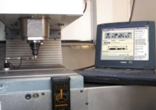 A ballbar monitors machine tool spindle movement as it follows a programmed circular path to that of a perfect circle. A ballbar monitors machine tool spindle movement as its follows a programmed circular path and compares the test path to that of a perfect circle. The ballbar consists of a telescopic bar with precision-machined magnetic ball and cup joints at either end. The bar houses a high-accuracy position sensor. One end of the ballbar typically mounts via a patented magnetic cup to the machine bed, while the ball at the other end attaches to a magnetic cup in the machine's spindle. The mounting configuration allows the ballbar to transcribe a hemisphere of motion in determining the machine's dynamic positioning accuracy. The ballbar's internal sensor contains two coils and a moving core and functions similarly to a linear variable differential transformer (LVDT). As the ballbar's length changes, the core moves inside the coils and causes a change in coil inductance. This inductance change is detected by sensor circuitry and converted to a position readout with a resolution of 0.1 microns (four microinches) and an accuracy of q0.5 microns (q20 microinches) at 20xC (68xF). The ballbar has only one wire connection and plugs directly (or via a USB adapter) into the RS232 port of any Windows-based PC with installed ballbar software. Notebook models provide maximum portability on the shop floor. 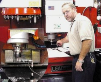 A typical ballbar test may sweep 100-mm radius, but tests in the range of 50 mm to more than 1,000 mm are possible. A typical ballbar test may sweep a 100-mm (4-in.) radius, but tests in the range of 50 mm (2 in.) to more than 1,000 mm (40 in.) are possible. Different lengths may be used to increase sensitivity to particular errors. For example, a longer length may be used to increase sensitivity to geometry errors such as imperfect squareness, whereas a very small radius may be used to highlight dynamic errors such as servo mismatch. A small circle kit is offered to enable test radii of as little as 15 mm (0.590 in.) to be carried out. Other accessories are available to enable the ballbar to be mounted between the spindle and turret on lathes and vertical turning lathes (VTLs). Ballbar tests typically take only ten to fifteen minutes and can be performed in full circle or on any angle - X-Y, X-Z or Y-Z arc traces. After the ballbar is installed, the machine is programmed to drive its spindle in a circular path that has a radius equal to the length of the ballbar. The ballbar tracks spindle movement to q0.5 micron (0.000020 in.), weighs errors based on the measured values and converts the ballbar data into an error-exaggerating polar plot of the machine's true movement. An experienced user can identify every error in the machine from this plot; however, sophisticated algorithms in the ballbar software produce a comprehensive diagnostic report that enumerates twenty-two different dynamic and geometric error values and then ranks them in order of importance. The overall positioning capability (true position) of the machine also is calculated. Reports also may be produced in accordance with ISO, ASME or JIS standards. Ballbar Preventive Medicine for Orthopedics ManufacturerSmith & Nephew Orthopedics (Memphis, TN) believes its machine tools must be just as flexible as the replacement hips, knees and shoulders that it produces. One of the world's largest makers of medical implants, the company finds that all 325 machine tools that create those implants must be capable of producing precision parts to Six Sigma. To keep its machines capable of producing tight-tolerance work in such variable production, Smith & Nephew regularly tests machine performance with the ballbar. When Richard Grimes, a calibration specialist, was put in charge of the company's CNC testing, repair and validation program in February, 1998, the performance of the plant's most critical machine categories was unacceptable. Using the Six Sigma measurement system, some machines were rated at only 3.0 Sigma. This caused much rework and scrap. Since Grimes implemented ballbar diagnosis, the plant's machine tools are now operating at true six Sigma or 0.0003-percent failure rate. "We now make better products and have less downtime because we can catch problems before they happen," says Grimes. Grimes uses the ballbar to check thirteen performance parameters. The company's quality department determined that those thirteen items combined must not be off by more than q0.003 in. "When new equipment comes in, I first test the machine with the ballbar," explains Grimes. "If a machine is moved, crashes or loses a spindle, I run a ballbar test. Regardless, each machine gets an annual test and will not run until it meets or exceeds our established specification." This regimen of periodic ballbar checkups and record-keeping allows Grimes to keep his huge army of CNC machine tools fit and flexible. Smith & Nephew's commitment to strict compliance and thorough machine evaluation assures that implants fit precisely and function flawlessly to return people to active enjoyment of life. Accuracies Soar for Aerospace Company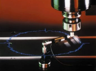 A ballbar takes the guesswork out of determining a machine tool's capabilities. Hamilton-Sundstrand (Rockford, IL) - a manufacturer of aerospace fuel-handling systems, auxiliary power units (APU) and wing flap actuation systems - ensures that its machines, both old and new, can cut it on tight-tolerance parts by using ballbar calibration. Whereas a machine tool may be designed and built to maintain a particular tolerance, wear and temperature changes will affect its capability to maintain factory specs, the company found. The Grand Junction, CO-based plant specializes in the machining of extremely tight-tolerance complex housings, forgings and hog-outs. Most parts have complex geometries that require four- and five-axis CNC equipment to produce typical aerospace tolerances of 0.001-in. true position, q0.0005-in. diameter and surface profile of 0.002 in. Personnel regularly monitor all of the company's CNC machine tools' performance parameters with quick ballbar tests. At the first sign of any nonconformance in parts, the machinist sets up and conducts a ballbar diagnostic test. The test checks fourteen different geometric parameters in each of the three machine planes tested - XY, XZ and YZ. Errors quickly are identified, then corrected by maintenance personnel. Additionally, periodic ballbar checks help reduce unscheduled downtime by tracking trends in machine performance. Problems can be identified before a machine tool goes down, allowing for scheduled repairs, rather than production crises. The ballbar also has helped reduce the time needed to complete routine preventive maintenance. Ballbar data allows the maintenance technician to determine the true extent of any corrective action that a machine may need. In many cases, the machine requires fewer adjustments than normally scheduled.
|
||


Related Content

Machining Center Spindles: What You Need to Know
Why and how to research spindle technology before purchasing a machining center.
Read More
The Trifecta of Competitive Toolmaking
Process, technology and people form the foundations of the business philosophy in place at Eifel Mold & Engineering.
Read More
How to Produce More Accurate Molds and Reduce Rework
Patented micro-milling process for manufacturing steel plate flat and parallel helps mold builders shorten mold build times and increase accuracy.
Read More
Moldmakers Deserve a Total Production Solution
Stability, spindle speed and software are essential consideration for your moldmaking machine tool.
Read MoreRead Next

Avoid Chasing CNC Variability with CAM
Moldmakers who produce tooling for medical devices and many other high precision molded products have been under increasingly greater pressure to reduce the variability of tooling components manufactured on their CNC equipment. One way they attempt to do this is by carefully adjusting offsets in the CAM program to compensate for variations in their equipment’s volumetric accuracy. Sometimes this works, other times not. Either way, the toolmaker pays a heavy penalty.
Read More
Are You a Moldmaker Considering 3D Printing? Consider the 3D Printing Workshop at NPE2024
Presentations will cover 3D printing for mold tooling, material innovation, product development, bridge production and full-scale, high-volume additive manufacturing.
Read More
How to Use Continuing Education to Remain Competitive in Moldmaking
Continued training helps moldmakers make tooling decisions and properly use the latest cutting tool to efficiently machine high-quality molds.
Read More