
The Feature Technology Feature of CAD/CAM
CAM software should have forward looking features that allow you to work in a traditional programming approach and to step up into a more organized environment that includes storing process knowledge and corporate experiences.


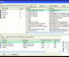
The macro database enables knowledge to be stored and organized for use on future jobs.
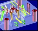
Greatly enhanced feature technology helps you simplify selections in a large model and standardize your programming process. Images courtesy of OPEN MIND.
CAM software systems promote many product features, like high-speed machining technologies, multi-axis machining, collision detection and simulation tools. However in recent years there also is another commonly dis-cussed feature called feature technology.


Defining a Feature
In most applications, feature technology and feature recognition are utilities intended to improve the programming performance for simple geometry like holes and pockets. In many systems, this may be limited to 2-D machining.
Granted, most machining applications have only basic requirements so this solution is often sufficient. Can feature technology apply to broader applications and more complex geometry?
Within integrated CAD/CAM processes, geometry features may be identified during the design step and automatically passed into the CAM environment. These features may be retained as corporate knowledge in a database of commonly used components and dimensions. However, most companies that produce molds and tooling are smaller supplier companies and receive CAD data from their customers. The suppliers often do not have a corporate enterprise system and generally use independent CAM software products from their customers. How do features work in these environments?
Of course, if the supplier has the same CAM software as the customer’s CAD system or has a direct translator, then the native CAD data can be imported. In some cases, the design feature information also is imported directly into the CAM system.
But in the general case, the CAM system must be able to create the feature information even if the data originates with neutral data such as STEP or IGES, without having intimate knowledge of the original design. In such a feature recognition process, the CAM software is able to recapture the feature information that was in the original design, or create it for the first time.
Breaking It Down Further
Yes, features are holes and pockets. But features also can be thought of in a more general way as any repeated geometry element or entity with a similar function. Features are a way to organize and add intelligence to CAD models. As models increase in size and complexity, the added organization can be extremely valuable. A feature can be a simple hole or a complex hole with multiple surface steps (counter-sink, clearance, chamfer, etc.), with threads, as a through hole or blind hole, a hole having orientation, or more.
And if a model has hundreds of holes, then the feature recognition and data organization can save the user from hours of laborious programming time and hundreds of error-proned selections. Similarly, pockets can have many descriptive parameters, such as open, closed, and corner and fillet radii.
These added descriptors begin to open the possibility that features can do more than identify geometry in a model. With this added information, you also can associate machining process knowledge to the features and then apply it to the actual geometry. These added levels of abstraction may seem like extra work, but the return is measured by reducing long selections or identifying a missed hole after the block is off the machine. There also is added consistency to the machining process by reusing the captured feature knowledge and process macros on future jobs.
How do you machine a blind hole or a through hole? How do you enter into an open pocket or a closed pocket, or machine multiple ribs and pockets that have different orientation or require five-axis machining approaches? By storing the machining processes in a macro database, the data is easily retrieved, whether by the same user or a different user. This approach allows for standards within an organization and greatly facilitates a low-risk way to introduce an apprentice or new programmer to the manufacturing environment.
Traditional sort and filter database functions allow large sets of process macros to be quite manageable. Depending on applications, macros can be organized by milling machine (standard or high-speed process), material (aluminum or steel) and various dimensions. And the database approach is scalable—working well with only a few stored macros or when large amounts of process knowledge are captured.
What is interesting about this approach is that each customer is storing their own local machining process knowledge—feedrates, step-downs, etc. The user gets the benefit of using productive CAM software as well as adding personal skills and experiences, including capabilities of manufacturing equipment, to further improve the performance of the system.
Feature Possibilities
Features also can be any repeated or similar geometric entity, not just a hole or pocket. Why can’t a feature be a strategy curve or surface—such as a drive surface, stop surface, profile curve, boundary curve or supplemental geometry like sync curves? Any geometric element that is selected repeatedly can be stored as a feature and then accessed as a feature instead of a specific element.
To get these benefits, the customer should be prepared to adapt to a feature technology paradigm by first preparing geometry and later storing machining process templates. While there is actually some resistance to this approach, many users also complain about the inability in their current software to reuse machining process knowledge in the face of a small design change. With feature technology, the programming of a similar part or design variation may be reduced to identifying features, importing macros and recalculating cutter paths.
Feature technology also can be used to organize the geometric specifications for niche applications. For example, turbomachinery components can have specific geometric entities. The feature technology can be used to select these entities (hub, shroud, blade surfaces, etc.) and then apply a set of application-specific machining strategies.
Turbomachinery components comprise a very well defined application set that is essentially an expert system within the general CAD/CAM environment. But there are also many market segments where it is hard to exactly anticipate the feature requirements as they may differ from shop to shop or application to application. Customized software solutions are quite expensive and can provide risk with compatibility with data structures of parallel and evolving corporate software standards.
Applying the Feature Concept to Unknown Data Types
The next step in the evolution of feature technology is to allow the user to define their own features, but within the context of standard software. The benefit is that each user can define the necessary ingredients of the features found in their applications and these features are retained as linked data to a standard software product. Without having custom software developed by the software manufacturer or third parties application vendors, the customer can readily upgrade the user defined features or UDFs from version to version as they become available.
Within the UDF, the user should have the ability to select specific surfaces and associate these with surface types in the application, such as a milling surface or a stop surface. The user also should have the ability to name the feature types within the local language used in their shop. This will improve the overall communication process between management, programmers and operators.
This ability to customize the software labels and centrally store process data is very attractive to many companies. Either standard features or UDFs can be an important ingredient for companies adhering to or striving toward ISO-9001 quality standards. The process-oriented solution and the use of a macro database—potentially controlled by an end-user’s ISO procedures—provide organization to a historically chaotic and individualistic NC programming world.
Looking Forward
Companies should look at CAM software as an investment rather than as an expense. The software should have forward looking features, such as advanced feature technology, that allow the company to work in a traditional programming approach, and to step up into a more organized environment that includes storing process knowledge and corporate experiences. All of this is possible with feature technology, with only a little investment and planning. Remember the old adage, “measure twice and cut once”.
![]()


Related Content

How to Manage Wall Thickness Changes in Your Mold Design
To ensure even filling and cooling, consider wall section transitions, corners and fillets, ribs and bosses, lip and rim designs and CAE flow simulation software.
Read More
It Starts With the Part: A Plastic Part Checklist Ensures Good Mold Design
All successful mold build projects start with examining the part to be molded to ensure it is moldable and will meet the customers' production objectives.
Read More
How to Improve Your Current Efficiency Rate
An alternative approach to taking on more EDM-intensive work when technology and personnel investment is not an option.
Read More
Mold Design Review: The Complete Checklist
Gerardo (Jerry) Miranda III, former global tooling manager for Oakley sunglasses, reshares his complete mold design checklist, an essential part of the product time and cost-to-market process.
Read MoreRead Next

CAD Interoperability: Its Costs to Mold Design and Mfg
An industry survey reveals some real data on how CAD interoperability is affecting mold shops.
Read More
Streamlining Processes with The Right CAD/CAM Package
VISI-Series provides the toolmaker a high level of productivity through its specialized applications, and offers dedicated solutions while eliminating the links between varying software suppliers and the solid-to-surface geometry conversions required by traditional systems.
Read More
How CAD/CAM Is Making a Programmer’s Job Easier
Arming yourself with the appropriate information will help you select the right software to help your shop work smarter not harder.
Read More