The Designer's Edge: More on Lifters
Lifters can cause read through and gloss issues due to a lack of cooling, deflection (as mentioned in last blog) and the lifter not being flush with the cavity surface.
Lifters can cause read through and gloss issues due to a lack of cooling, deflection (as mentioned in last blog) and the lifter not being flush with the cavity surface. Typically, it is sufficient to have the lifter sub-flush from the cavity surface at 0.002 to 0.003 inch. This prevents dragging or sticking.
Also when any rib details are in the lifter and cavity against which the lifter travels, the rib detail in the lifter should be wider by 0.001 to 0.002 inch. This reduces dragging and sticking when traveling against the rib detail in the cavity. Although this is standard, many times it is necessary to have the lifter flush with the cavity surface to eliminate visual defects on the part. Also, if the lifter has sharp edges, it can peel up plastic leaving flakes in the tool, creating defects on the next part. In some cases, a slight texture on the lifter surface can camouflage read through.
Lifter pre-load is another critical spec. This is also referred to as timing the lifter, which is established by the moldmaker. Pre-load is what ensures that the lifter is held down during the molding process. If the lifter is built to the exact length, plastic pressure on the lifter cavity details can pull the lifter up. This causes flash, dimensional issues or read through.
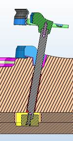
The lifter is attached to the ejector plates with a slide and gibs, which have some clearance to allow for mechanical movement. In most cases, the lifter rod or shank will be shortened 0.002 - 0.003 inch to accommodate for these clearances and to ensure the lifter is secure during mold close.
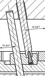
For one job I refurbished a mold with new lifters and the parts produced were out of spec 0.007 inch with the clip detail. I knew they were properly positioned before sampling the mold, which was verified after evaluating the lifters. The lifters were on seven degrees, but had too much unsupported length and no shut-off shelf. The plastic pressure was deflecting the lifter shank pushing the lifter down during the injection process. In this case, we raised the lifter (the opposite of pre-load) to accommodate for this issue. Not the greatest solution, but redesigning the mold was not an option at this point.
If the lifter or detail is below the cavity surface on the molded part, it is likely being pushed down from plastics pressure. The only way it can be pushed down (if timed properly and verified), is from cavity pressure causing deflection on the lifter shank. Ensuring the lifter has minimum unsupported length with bearing surface, guides or bushings or a buddy/helper pin are some solutions.
In the next blog I will get into fitting the lifters and wear surfaces.


_300x250 4.png;maxWidth=300;quality=90)


