
The Art of Automation
Learning to harness the power of an automated CAM system is not only good for business, it preserves best machining practices for the future.


Although high-speed toolpath looks like it takes longer to cut, it is actually much faster than traditional toolpath because a constant chip load allows the cutter to handle a larger depth-of-cut and a greater step over. The swirling motion means that the cutter is in constant contact with the material and the feedrate for the linear moves from the end of one pass to the start of the next can be set to the maximum the NC machine can handle.
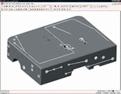
Every hole on every face of a part model can be recognized with a single click. The properties of every hole—such as depth, chamfer, diameter, counter bore and axis orientation—are analyzed and preserved as well to facilitate automated drilling.
The CAM system can automatically cover holes and other openings in a part model before the toolpath is generated. The system can also automatically delete the covers as soon as the toolpath is complete. The depth of areas to be covered is completely controlled by the user at each step in the roughing, re-roughing and finishing process.
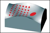
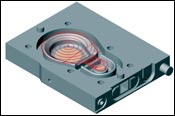
When a CAM system automatically covers openings—such as these holes—it’s important that the new surfaces conform to the overall shape of the surface being machined, no matter how complex.
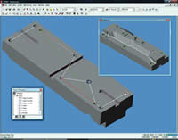
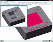
Automatic feature recognition automatically recognizes every machinable feature on a part model, including the holes, open pockets and groove on this model. Holes are automatically grouped by type and size and all holes can be connected and spot drilled along an optimized path. Images courtesy of DP Technology Corp.
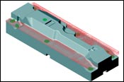
High-speed roughing passes start with a spiral movement in the largest calculated machinable area. Spiral and arc moves are used throughout the cut to keep the cutter on the part, not in the air. The CAM system maintains constant knowledge of the cutter and the remaining stock to calculate a constant chip load that prevents tool breakage even at double the feedrate.
Myth or fact: CAM systems that offer push-button automation tell machinists how to program their parts. If you said it’s a myth you’re absolutely right. It’s actually the other way around. In an automated CAM system, the programmer dictates to the system how parts are to be machined.
So how did this myth become so prevalent? It probably started when CAM software developers, in an attempt to assist users new to automation technology, pre-loaded what were thought to be industry-standard machining parameters into the system. We all know that machinists have their own thoughts on the matter, so it’s impossible to come up with any “standard” that will make everyone happy.


The pre-loaded defaults were only meant to serve as examples to guide the user, but they were misconstrued as vendor recommendations. In other words, it seemed as though the system was telling programmers what to do.
It’s time to dispel the myth and provide some concrete examples showing how to make an automated CAM system do what it’s supposed to do: make your job faster and easier.
What Is Push-Button Automation?
First of all, “push button” means that with only a few clicks a CAM user can produce one or more machining operations. The number of clicks required to produce the NC code depends on the level of automation a company decides to build into the system. A certain amount of user interaction is still required to direct the CAM system in what task to perform. Typically, users will start by automating one or two simple tasks and then add more automation as they become more comfortable with the technology.
For each click, the system takes only a few seconds to perform a task that usually takes several minutes for a person to do. But the system does not define the task on its own. The owner of the CAM software provides the system with a set of instructions that tell the application what to do.
The Foundation of Automation
Automation starts with a database that stores and organizes information about conditions in the shop and how the company machines its parts. The purpose of the database is to create a virtual replica of all the cutting tools, raw material and CNC machines that actually exist on the shop floor. Even more important, the database stores proven machining parameters and processes so the CAM system can make the best choices when a program is created.
Some CAM systems provide a database with pre-loaded data. If so, take a look to see whether any of the existing data is a close match to the actual conditions in the shop. This is the data that can be easily edited to create an exact match. Get rid of everything else. That’s right. Delete any data that has no relevance to your own shop and how you machine your parts. Otherwise, the system could inadvertently choose a tool or cutting strategy that does not match your shop floor conditions. Many users are reluctant to delete data, but the original data can always be reloaded from the installation CD.
Automated CAM systems also store machining preferences for different types of operations. This is where users begin to get a real taste of the limitless possibilities available through automation. For example, if a shop always cuts hardened materials on its best high-speed machine, a dedicated group of machining preferences can be stored for that particular task. Or, separate sets of machining preferences can be set up to meet the requirements of different customers. If a shop machines groups of similar parts, preferences can be stored for each family of parts. A database can expand to store almost any combination of shop floor data and machining preferences.
Once data is set up in the system, it can be shared and programmers can begin using it immediately. When a part file is opened, the first task is to tell the system something about the job at hand, such as the material being machined, which machining preferences to use, and possibly the type of part being machined. This gives the system enough information to retrieve the correct data from the database and automatically fill in machining parameters as operations are created.
A simple task like setting up shop floor data in a database lets the CAM system:
- Automatically select the correct cutting tools based on the part material and type of operation
- Automatically calculate appropriate spindle speeds and feedrates based on the part material, tool material, depth-of-cut and NC machine
- Automatically select user-defined machining preferences
Feature-Based Automation
Another aspect of push-button automation is the use of machinable features. Solid models in CAD/CAM systems are built from a set of interrelated features. In a CAM system, the capability of these features to describe a model is extended to include machining information that becomes integrated into the part model. That way, any update to the model will automatically update the machining data at the same time.
Most CAM systems have standard milled features like pockets, holes, slots, bosses, grooves, and so on, plus specialized turning and wire EDM features. A true advantage is when the system allows a user to take the definition for a standard feature like a pocket and customize it to become a feature unique to an industry, like a runner or gate, with its own machining process that adapts to the shape of the feature. The CAM system can then automatically recognize a runner on a part model and know how to machine it according to a company’s specifications.
The automatic recognition of features is a key element of automation. A perfect example is the recognition of holes. CAM systems do an excellent job of recognizing holes in CAD models. In this case, every hole in a solid model can be recognized with a single click. Since CAM features also contain machining properties, the type, size, depth, chamfer or counter bore of each hole is recognized as well. The work plane for each hole is embedded in each feature as well, which is critical in determining the orientation of the part during drilling. Similar size holes can be grouped together to reduce tool changes, all holes can be linked and spot drilled first, and holes with a diameter too large for drilling can be recognized as milled holes. With full automation, feature recognition can kick off a process that generates every drilling operation in an optimized sequence without human intervention.
Features further enhance automation by allowing the system to:
- Automatically recognize and drill (or mill) holes
- Automatically recognize and machine standard and custom features
Automatic Covering of Openings
Automation is not all about data and features, though. Many CAM systems have sophisticated automation integrated into the software that analyzes the part geometry. This is especially important to moldmakers since molds are composed of a mixture of complex surfaces and standard features that must be machined using different techniques. Plus, different surface areas are typically machined in a progression of steps using a variety of roughing, re-roughing and finishing strategies depending on the underlying geometry.
To help programmers ease these constraints, automated CAM systems can intelligently cover openings in a part model so the tool can machine over them as if they aren’t there. This prevents the perilous problem of the tool plunging unexpectedly into an opening while milling along an otherwise smooth surface. The system analyzes the model to automatically generate coverings before the toolpath is calculated. The coverings can then be deleted automatically as soon as the operation is finished or saved for later use by other operations. This saves the programmer from manually and tediously creating surfaces to cover areas that will be machined later in the process.
- Automatically cover holes on any surface, including holes tilted at an angle
- Automatically cover openings that have complex profiles
High-Speed Roughing Automation
Roughing is one area where a shop can significantly reduce machining time with a CAM system that uses advanced algorithms to calculate the shape of the toolpath based on a constant tool load. Specialized roughing operations produce an even chip load over the entire course of a cut by taking two factors into account: (1) the shape of the part geometry at each incremental depth and (2) the amount of engagement between the tool and the material at any given position in the toolpath.
The system automatically adjusts the shape of the toolpath and the feedrate whenever it detects that the cutter is fully engaged in the material. The resulting smooth, flowing tool motion can run at much higher feedrates, spindle speeds and depths-of-cut because there is considerably less pressure on the tool. The tool won’t get buried and snap.
- Produce a better finish with adaptive roughing passes that conform to the shape of the part
- Rough parts faster with a constant chip load
- Prevent excess pressure on the tool that can cause the tool to snap
- Reduce air cutting with morph and spiral toolpaths that keep the tool on the part
Automatic Conversion of Three-Axis to Five-Axis Toolpath
For hard milling applications, companies are using shorter tools to improve rigidity. The problem is that these tools cannot reach into deep cavities using standard three-axis milling. CAM companies have resolved this issue by allowing the user to cut as much of the toolpath as possible with three-axis milling strategies. When the software senses a tool or holder collision on a three-axis path, it will split the toolpath and convert it to a five-axis cutter path that minimizes the inclination of the tool to save positioning time.
- Use shorter, more rigid tools
- Intelligently switch between three-axis and five-axis toolpath within the same operation
Preserve Machining Knowledge for the Future
As talented toolmakers leave the field and fewer workers enter it, the importance of capturing the knowledge of skilled workers is critical to moving a business forward.
Companies spend a lot of money training a worker to become a good toolmaker. The costs include years of training on machines, computer hardware, software, workholding techniques, and best moldmaking practices plus salary, benefits, utilities, insurance, and more. The knowledge is embedded in the worker, not the company, so when that employee leaves either for retirement or for another job the worker carries those costs and that knowledge out the door.
To retain the best toolmaking knowledge, a company must be able to capture and store it in a way that other toolmakers and trainees can use. An automated CAM system allows a company to put manufacturing process data that has been optimized over the years onto a computer, where it can be shared and used by anyone in the company with permission to access that information.
Storing knowledge within a CAM system lets the computer perform repetitive tasks, allowing highly skilled workers to spend more time improving manufacturing processes. Sophisticated CAM automation gives a mold company the advantage of allocating its valuable human resources to strategic endeavors that enhance the competitiveness of the entire business.


Related Content

How to Use Automation to Minimize Mistakes and Speed Mold Build Process
A guide to capturing and reusing company knowledge and experience with software automation.
Read More
How to Automate Process and Design
Moldmakers can improve their operations and stop wasting time by taking these six steps for process and design automation.
Read More
Five-Axis Graphite Mill With Automation Debottlenecks Electrode Machining
Five-axis electrode cutting enabled Preferred Tool to EDM complex internal screw geometry on an insert that otherwise would have had to be outsourced.
Read More
How to Machine Micron-Level Precision Molds in One Try
On-machine measurement intelligence and modification technology helps mold builders overcome machining variables and quickly produce micron-level tolerances.
Read MoreRead Next

CAM Technology Trends
More than the products themselves, the CAM industry is changing the way it does business and moldmakers should take note.
Read More
Knowledge-Based CAD/CAM: Separating the Hype from True Machining Intelligence
CAD/CAM systems that incorporate knowledge-based machining increase moldmaking efficiency by requiring less time to program parts.
Read More
Choosing the Right Knowledge-Based CAD/CAM System
CAD/CAM systems that offer knowledge-based machining deliver tremendous savings in both time and costs, but only when the system meets your specific needs.
Read More