
Taking Control Over the Molding Process
How to gain better control over the molding process and solve common part defects.
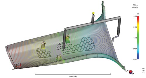
Figure 2 - The lines represent the position of the flow front at consistent time intervals. The distance between the lines shows the flow front’s velocity. Flow-front acceleration can be seen just left of the delayed gate (center), while stagnation of the flow front can been seen above and below the delayed gate. Figures and graphs courtesy of Synventive Molding Solutions.
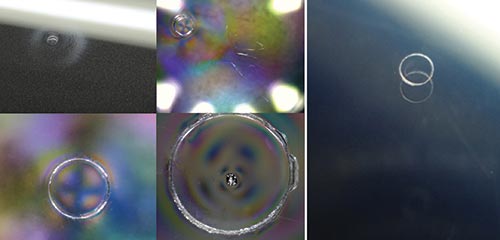
Figure 3 - The figure on the left shows common gate-area defection on direct- gated parts. Excellent cosmetics (right) can be achieved by controlling the opening and closing movement of the valve pin.
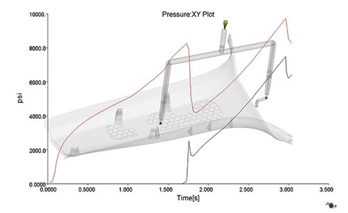
Graph 1 - This graph illustrates the pressure inside the cavity at each hot runner gate. Sudden spikes and drops cause flow-front acceleration and stagnation. The valve pin closes off the gate.


Having proper control over the molding process is critical to achieving excellent part cosmetics, and new advances in hot runner technology are providing a level of control not previously available. This additional control allows molders to solve cosmetics problems, even for the most challenging applications.
Gate Options
Hot runner systems fall into two main categories that pertain to gate function: thermal gate systems and valve gate systems. Thermal gates have no moving parts. After the cavity is filled and the polymer begins to freeze in it, plastic freezes inside of the hot runner gate as well. When the mold opens and the part pulls off the A side of the tool, the solidified plastic in the gate breaks; some of this frozen plastic stays with the part and some stays behind in the hot runner gate. What remains in the gate acts as a dam, preventing molten plastic from flowing out while the tool is open. Then, when plastic is injected into the hot runner on the next cycle, the pressure behind this plastic dam forces it to shoot out, opening the gate again so plastic can fill the part (see Figure 1).


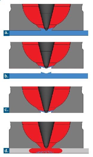
Figure 1 - Thermal Gate
a. Plastic freezes inside the hot runner gate.
b. The part pulls away and plastic breaks in the gate, leaving a "dam" behind.
c. The plastic dam prevents molten material from flowing out of the gate.
d. Injection pressure breaks the plastic dam, allowing the part to fill.
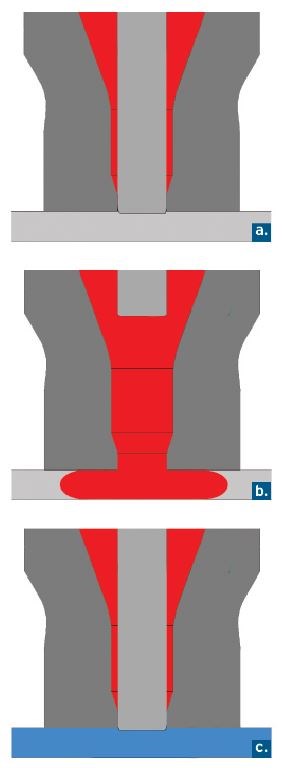
Figure 1 - Valve Gate
a. The valve pin is forward, closing off the gate.
b. The valve pin retracts, opening the gate and allowing the part to fill.
c. The valve pin closes off the gate.
Valve gates, on the other hand, are more complex because they do have moving parts, yet their theory of operation is much simpler. At the start of the cycle, the valve pin is forward, closing off the gate. The pin is then retracted, making a path for material to be injected into the part. Following the hold phase, the pin is closed again. This shuts the gate and prevents drooling during the next mold-open cycle.
Valve gates offer much more control over part filling than thermal gates, and, as mentioned earlier, this additional control can greatly improve cosmetics. There are limitations, however. The molder determines when to open and when to close the pin, but he has no control over how far or how fast the pin moves.
Pin Control: Movement and Speed
Hot runner technology advances offer various levels of additional pin control. Some enable the molder to slow the pin opening speed for the entire stroke. Others allow the pin to
be slowed for a set distance after which the pin returns to
full speed. Still other technologies allow for complete control over the pin opening, closing and stroke.
Controlling a valve pin’s movement can help eliminate defects. This can be achieved with tool-based molding tech-nology that moves much of the control from the injection molding machine into the hot runner.
Controlling the opening speed of the valve pin is particularly beneficial in cascade molding, which is used to eliminate weld lines on multi-gated parts. In this type of molding, the part is initially filled from one gate while opening of the other gates is delayed until the flow front passes each of them. The delayed gates are then opened, introducing the melt behind the original flow front and preventing the formation of weld lines. Although this type of molding is able to improve cosmetics, by eliminating weld lines, its sudden flow-front accelerations and stagnations can cause other defects.
Figure 2 illustrates what causes these sudden changes in flow-front velocity in conventional cascade molding. The part shown is initially filled from the hot-to-cold gate on the right, and the direct gate in the center of the part is delayed until the flow front passes it. This prevents the formation of a weld line. The lines shown on the part represent the flow front’s position at consistent time intervals. Lines close together indicate that the flow front is moving slowly, while lines further apart show that the flow front is moving faster.
Graph 1 shows the pressure inside the cavity at each color-coded gate as the part fills. As the flow front is pushed toward the delayed gate, the pressure at the first gate builds (red line). Although the pressure in the cavity near the delayed gate is zero (black line) as the flow front reaches it, pressure is building behind the closed valve pin. When the pin opens at 1.8 seconds into the fill, the pressurized plastic is allowed to burst into the cavity. This can be seen in the graph as a sudden spike in pressure at the delayed gate (black line) and a sudden drop in pressure at the initial gate (red line). The sudden spike in pressure at the black gate causes an acceleration of the flow front near that gate, while the sudden drop in pressure at the red gate causes the flow front away from the gate (near the edges of the part) to stagnate.
The relative distances between the lines in Figure 2 show the changes to flow-front velocity, which often show up on the molded part as lines of differential gloss. By slowing the valve pin’s opening speed, you can drastically reduce the sudden flow-front velocity changes. In many cases, this eliminates the resulting defect.
There are many types of technologies available that reduce the valve pin’s opening velocity. Some reduce the pin speed for the entire stroke of the valve pin. Generally, these technologies have manual flow-restrictor valves in the hydraulic circuit which control the flow of the hydraulic fluid to the valve gates. They tend to be less expensive than higher-end technologies, but they slow the valve pin speed for the entire opening stroke. This can create excessive shear, shear heating, pressure loss and stress that can cause other defects.
Other technologies enable the user to slow the initial opening speed of the pin for a set distance. This permits a controlled release of the pressured plastic behind the pin. Then the pin is opened at full speed to facilitate filling the remainder of the part while avoiding excess shear and the associated defects. This two-stage speed control is extremely important when there is significant flow length remaining after the delayed pin.
Still other hot runner developments give the molder complete control over the pin’s movement by allowing him/her to set multiple speeds, acceleration and stroke for the valve pins’ opening and closing movements. This control can eliminate gate area defects and provides additional drop-to-drop balance.
Figure 3 (page 51, left) shows common gate area defects when direct-valve gating onto transparent polycarbonate. The image on the right shows the same gate when the valve pin’s opening and closing speed is controlled.
More advanced technology goes beyond controlling a valve pin’s position and movement and adds a pressure sensor in the cavity or the hot runner system. This enables the molder to set individual fill and pack pressure profiles for each hot runner nozzle, and takes the pressure control away from the machine and moves it to multiple points of injection within the mold. This supplies a level
of nozzle control that has opened the door to new applications.
Summary
Control over valve pin movement and speed is a new focus area in hot runner development. The technologies reviewed here allow for new applications, previously unobtainable cosmetics, lower scrap rates, better balance, higher production rates, complex geometries and the use of extreme family tools. Understanding their capabilities will help you select the one that is right for your next chal-lenging application.


Related Content

6 Ways to Optimize High-Feed Milling
High-feed milling can significantly outweigh potential reliability challenges. Consider these six strategies in order to make high-feed milling successful for your business.
Read More
Hands-on Workshop Teaches Mold Maintenance Process
Intensive workshop teaches the process of mold maintenance to help put an end to the firefighting culture of many toolrooms.
Read More
Treatment and Disposal of Used Metalworking Fluids
With greater emphasis on fluid longevity and fluid recycling, it is important to remember that water-based metalworking fluids are “consumable” and have a finite life.
Read More
Machining Center Spindles: What You Need to Know
Why and how to research spindle technology before purchasing a machining center.
Read MoreRead Next

Understanding Electric Valve Gates
What the right electric valve gate system means to the moldmaker and his customers.
Read More
How to Use Continuing Education to Remain Competitive in Moldmaking
Continued training helps moldmakers make tooling decisions and properly use the latest cutting tool to efficiently machine high-quality molds.
Read More
How to Use Strategic Planning Tools, Data to Manage the Human Side of Business
Q&A with Marion Wells, MMT EAB member and founder of Human Asset Management.
Read More