
Spindle Design for Maximum Performance
Understanding the influence of all the forces - from the type of insert to the machine base - is the key to maximum spindle, and thus, maximum machine tool utilization.


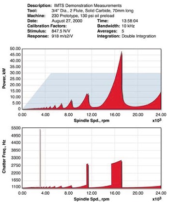
Figure 2: This power vs. speed diagram illustrates the spindles's chatter frequencies and power availability at specific rpms.
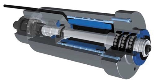
Figure 1: A new OEM machine tool spindle design features ceramic triplex front bearing sets and a rear ceramic roller bearing set.
Up to this point, in an effort to increase machine tool performance, a variety of methods have been provided as part of the solution to the many problems encountered by moldmakers. Increasing speeds and feeds are now a given; more powerful external drives or integrally motorized spindles have become readily available; and new tooling technology - including advanced coatings and tooling designed for increased feedrates - have recently hit the market . In addition, the important requirements of balanced spindle, tool holder and tooling have been met. The final piece needed for the high-speed machining puzzle is a reliable cutting performance prediction of the total system dynamics to achieve optimum horse-power-to-material removal rates.
Energy expended generating unwanted vibrations is the major drawback to obtaining the maximum power in material removal. The question that needs to be answered is this: where do most typical vibrations come from when related to milling? This depends on the method that excites the structure. The structure can be anything that moves on the machine - not just what rotates and translates, but most importantly what vibrates. Is chatter caused solely by imbalance? No. The following three items are the primary sources of spindle vibrations: imbalance occurring at the spindle rotation frequency and/or harmonics; the cutting force vibration occurring at the tooth passing frequency and/or harmonics; and regenerative chatter occurring at or near one of the vibrational modes of the system.


The energy for regenerative vibration comes from the cutting process. The sooner one understands the source of vibration the sooner a more productive material removal process can be produced. How often has a machine tool OEM pointed the finger at a spindle or tool as the problem? Or, how often has the spindle maker blamed the cutting tool or machine maker? And lastly, how often has the cutting tool maker said that the spindle or machine was not capable of using the tool properly? Understanding structural dynamics can eliminate "finger pointing" and help everyone involved be more productive. The sources of many of these problems can be identified by understanding vibratory systems and structural dynamic analysis.
Analysis Benefits
Analytical tools are available to measure the frequency response functions in order to predict spindle chatter through stability models. These models can generate insight for the engineer into the operation and cutting performance. Outputs include what spindle speed and depth of cut are critical for the machine/spindle/tool combination. Cutting forces are given as instantaneous and as an average. Dynamic tool deflections can be predicted (see Figure 2).
The computer stability modeling emulates the milling process by simulating material, cut direction, width of cut, cutting mode (such as slotting), axial depth of cut, spindle speed, nominal chip load and tool rotations. Simulation parameters include: starting rpm, ending rpm, rpm increment, starting axial depth of cut, ending axial depth of cut, depth of cut increments and number of iterations. The thousands of multiple simulation runs generated by the software give a good indication of the machine tool stability. Other modeling software can help to determine skidding in the bearings as a function of preload, static radial load and rotational speed. Calculating the spin roll ratio over the range of changes in the stiffness as a function of load leads to accurate bearing life and thermal signature prediction.
Structural dynamic system analysis tools can be used throughout the entire machine tool utilization process - from design to production. Initial modeling is used in the design stage. Analysis can be used to validate the design and ensure quality. Quality checking and process repeatability testing analysis confirms predictions. It also can be used to verify subassembly assumptions during installation and finally to confirm process analysis during actual production.
Often the most difficult problems are dynamics issues. Static thought processes will not work. For example, an original spindle design could only deliver about 10 percent of the power capacity - about 7.5 kW. A modified spindle could deliver 100 percent - about 75 kW. This demonstrates a tenfold decrease in roughing cycle time. Modal stiffness increased by only 26 percent, whereas modal damping increased by 456 percent. This example was using an endmill with a collet tool holder. The material was HSS and the diameter was two inches. There were two flutes, with a tool holder face to tool tip distance of 6.5" and a gage line to tool tip distance of 12.625". The key to the increased performance is the product of the modal stiffness and modal damping.
In summary, structural dynamic analysis of the complete machine tool is required to accurately predict and design in high cutting performance. The spindle must be designed, built and dedicated to the specific task at hand and is not easily changed to achieve maximum performance for a wide range of materials and processes. However, if near maximum material removal rates need to be achieved - resulting in a tenfold increase in productivity - there is a way to accomplish it. For the first time accurate computer analysis tools are available to achieve truly high material removal rates in dependable systems.
The future holds that experience will develop variable dynamic systems that can combine a wider range of tools, materials and removal methods.
This article is courtesy of Dyna Drive, Inc. (Solon, OH) in cooperation with SKF and Russell T. Gilman, Inc.
For more information contact Tom Klahorst, vice president sales for Russell T. Gilman, Inc. (Grafton, WI) at (800) 445-6267 or via e-mail at tklahorst@rtgilman.com.


Related Content

OEE Monitoring System Addresses Root Cause of Machine Downtime
Unique sensor and patent-pending algorithm of the Amper machine analytics system measures current draw to quickly and inexpensively inform manufacturers which machines are down and why.
Read More
Control Helps Push the Limits of Five-Axis Micro Mold Machining Accuracy
Toolmaker quickly meets the demands of critical medical device manufacturers with a new five-axis machine tool equipped with the right control technology.
Read More
The Trifecta of Competitive Toolmaking
Process, technology and people form the foundations of the business philosophy in place at Eifel Mold & Engineering.
Read More
Machining Center Spindles: What You Need to Know
Why and how to research spindle technology before purchasing a machining center.
Read MoreRead Next

Are You a Moldmaker Considering 3D Printing? Consider the 3D Printing Workshop at NPE2024
Presentations will cover 3D printing for mold tooling, material innovation, product development, bridge production and full-scale, high-volume additive manufacturing.
Read More
How to Use Continuing Education to Remain Competitive in Moldmaking
Continued training helps moldmakers make tooling decisions and properly use the latest cutting tool to efficiently machine high-quality molds.
Read More
Reasons to Use Fiber Lasers for Mold Cleaning
Fiber lasers offer a simplicity, speed, control and portability, minimizing mold cleaning risks.
Read More