
Special Coverage: Hot Runner Technology
MoldMaking Technology provides special coverage of hot runner technology as a supplement to the October 2017 magazine. Read the entire supplement here, or check out the supplement page to read each article individually.
Six Key Factors for Evaluating a Hot Runner System (Image 1). This four-drop hot runner system has pressed-in tubular heaters. Photo courtesy of Incoe Corporation.
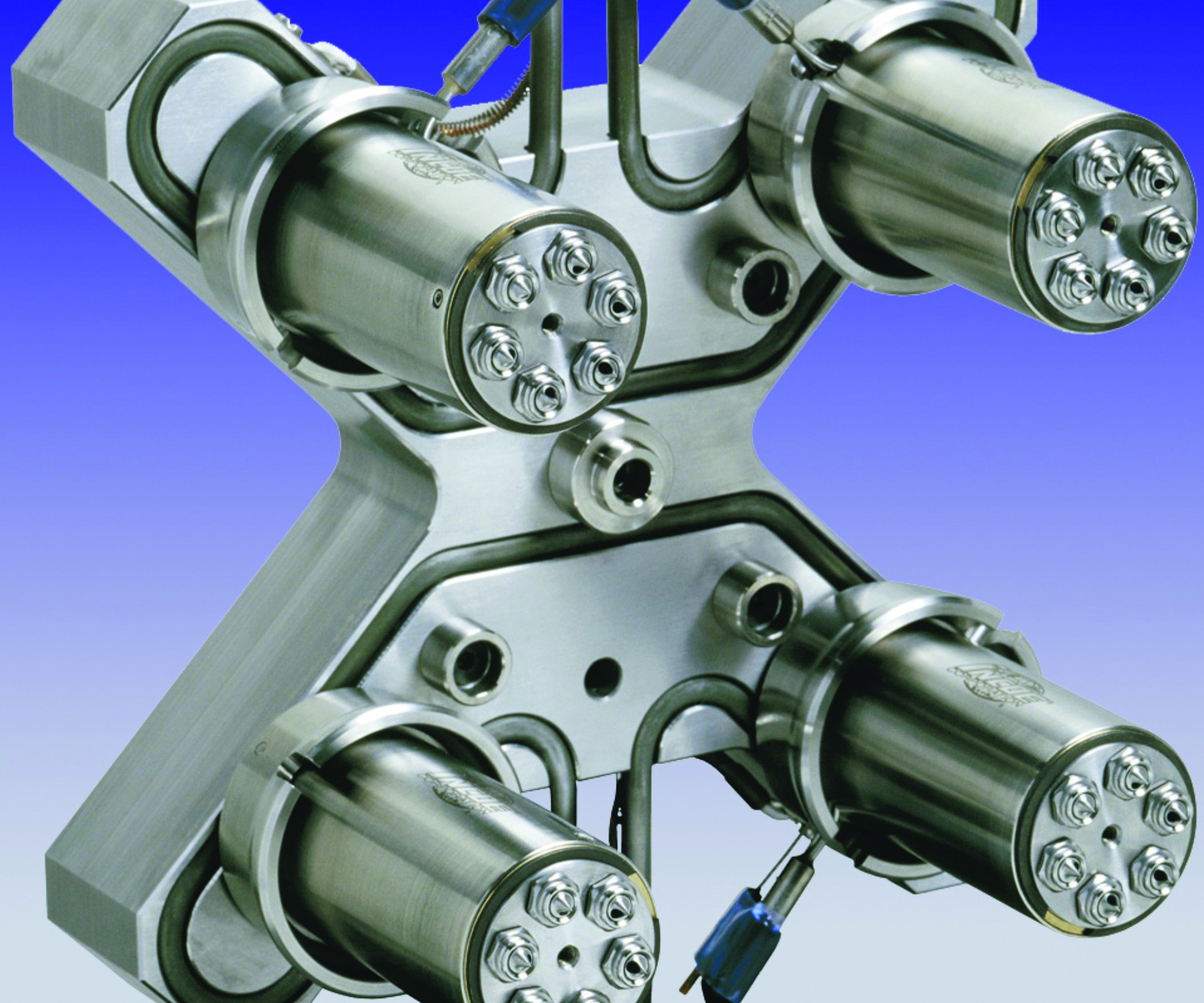
Six Key Factors for Evaluating a Hot Runner System (Figure 1a). This image shows the location after additional thermal expansion. Notice the effective flow channel is less here. Images courtesy of Beaumont Technologies and the AIM Instititute.
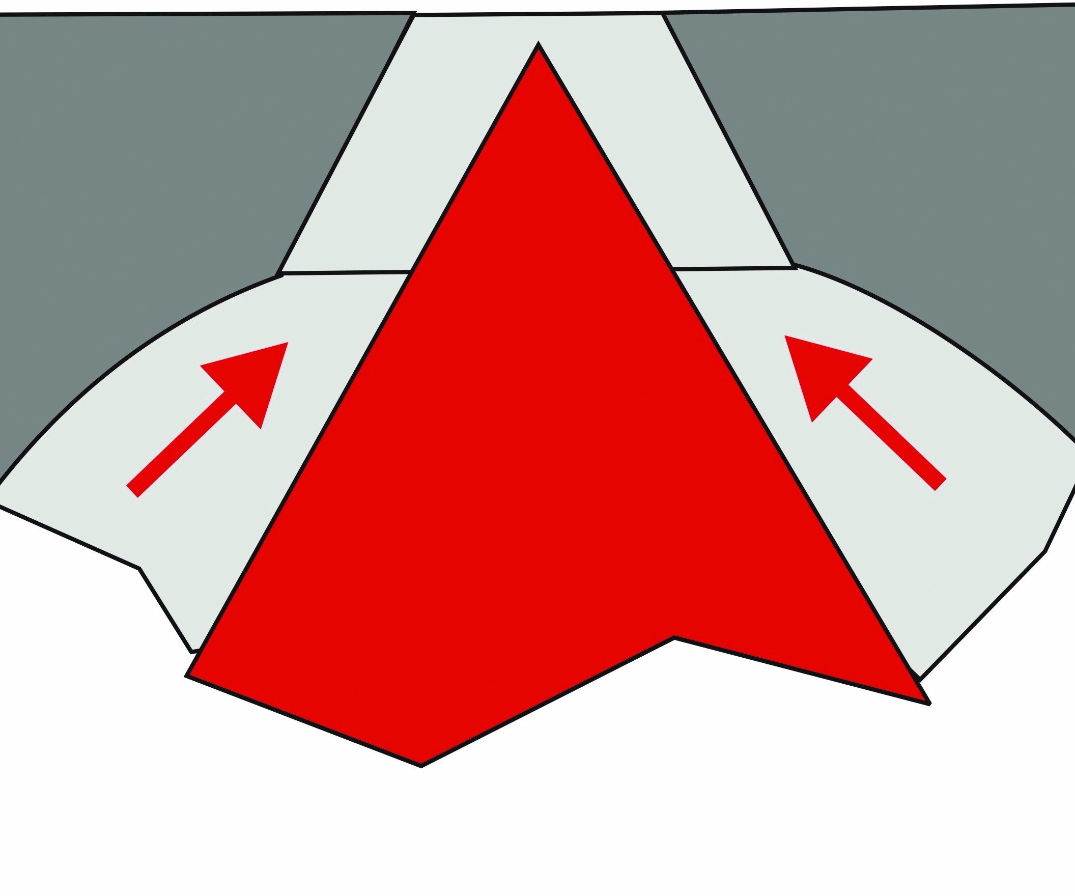
Six Key Factors for Evaluating a Hot Runner System (Figure 1b). The hot tip's natural position with expected thermal expansion. Images courtesy of Beaumont Technologies and the AIM Instititute.
Six Key Factors for Evaluating a Hot Runner System (Figure 2). Checking the uniformity of the stack height across all nozzle tips is important to avoid points of tolerance stack-up issues shown here. Images courtesy of Beaumont Technologies and the AIM Instititute.
Six Key Factors for Evaluating a Hot Runner System (Figure 3). The natural flow path of the polymer through a branched runner and around a corner is shown in red. Potential stagnant locations are indicated in blue. Images courtesy of Beaumont Technologies and the AIM Instititute.
Six Key Factors for Evaluating a Hot Runner System (Figure 4). This leaking manifold caused plastic to encase the hot runner wiring. Images courtesy of Beaumont Technologies and the AIM Instititute.
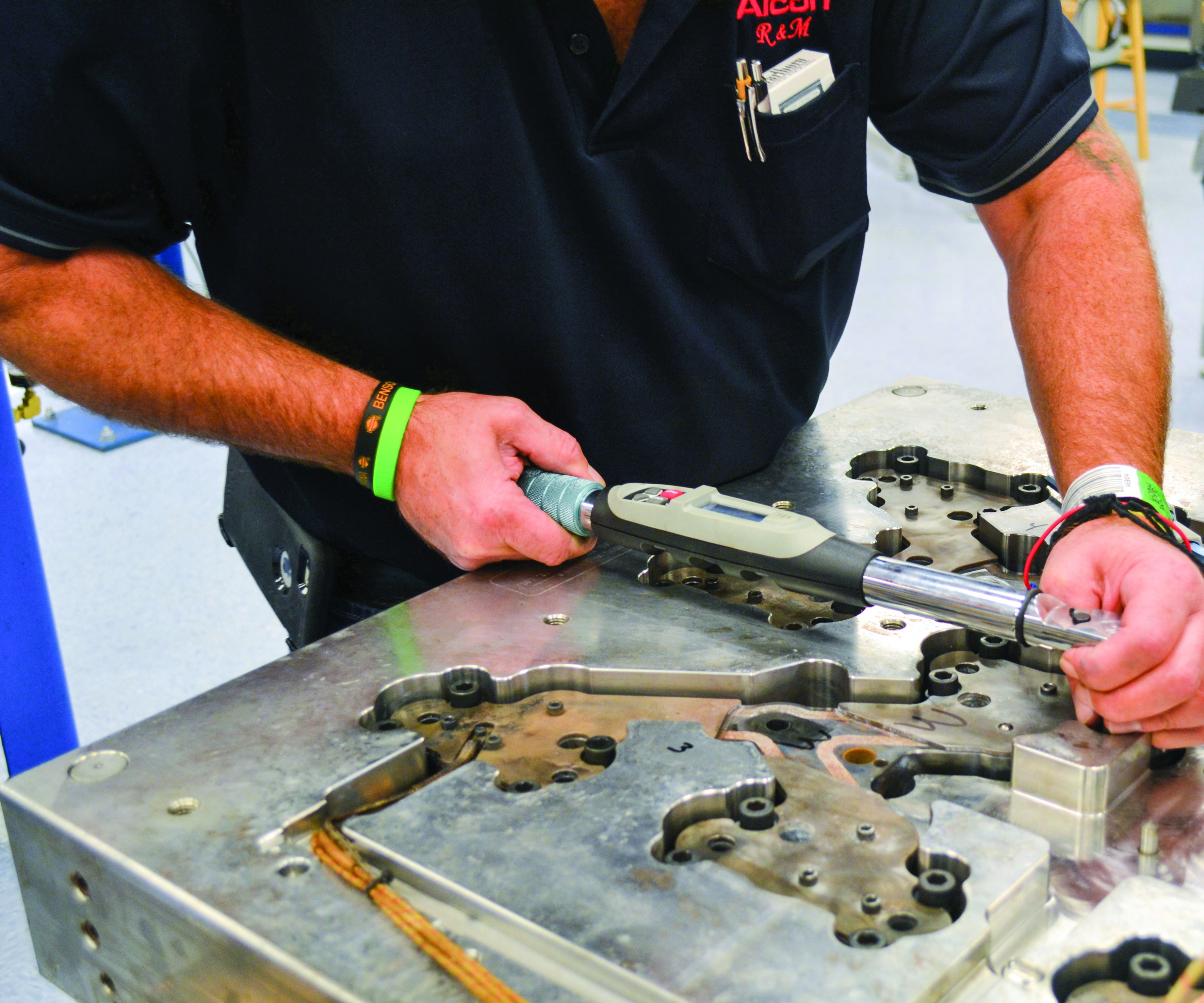
Breaking Down Hot Runner Maintenance (Image 1). Improving a manifold’s maintenance plan requires specific skills and knowledge of its functioning areas. Images courtesy of MoldTrax Maintenance Solutions.
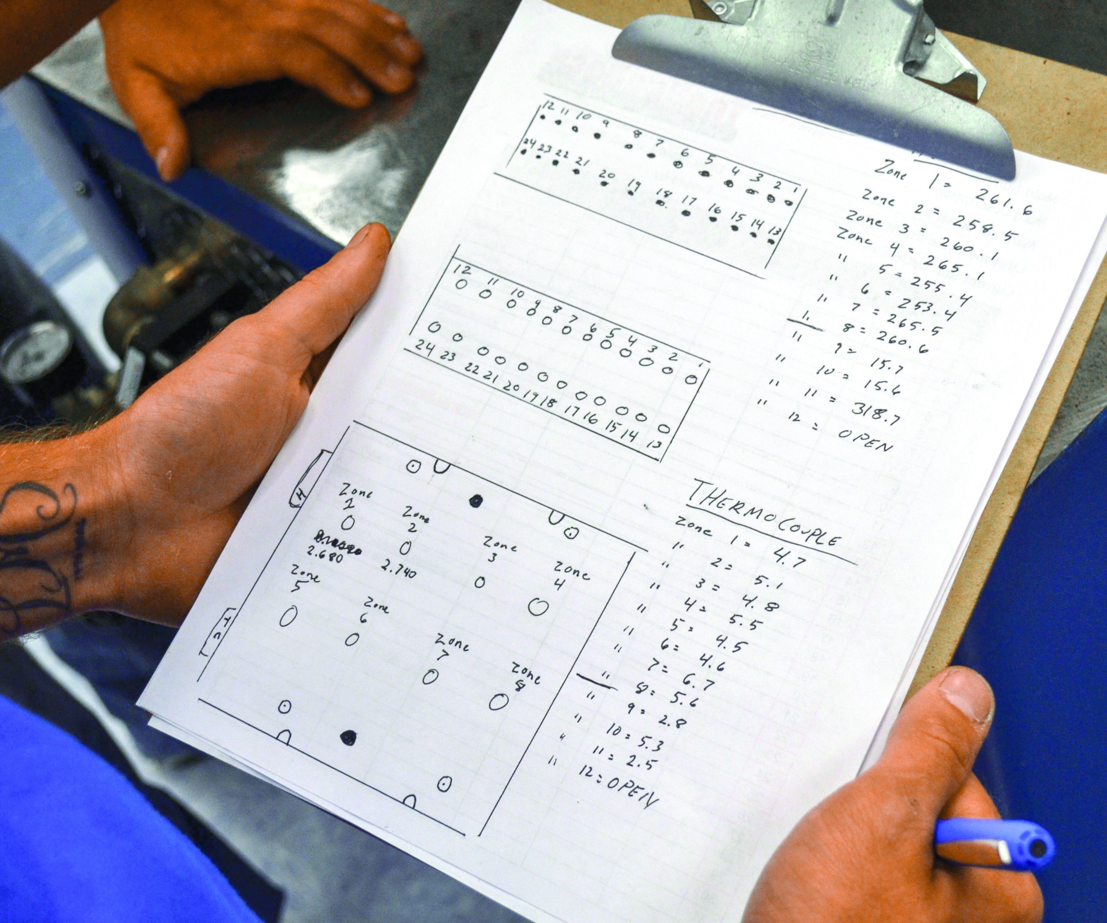
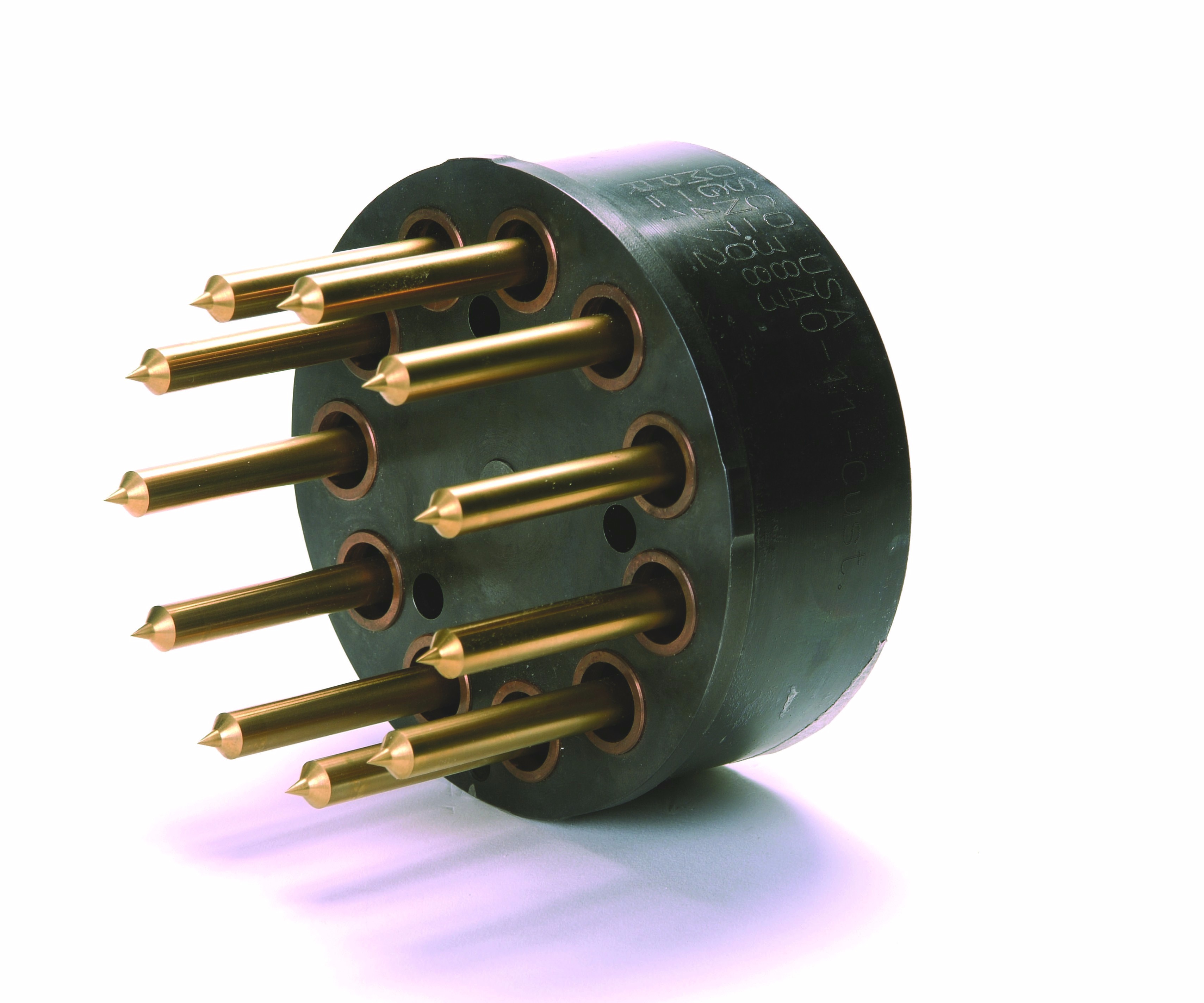
Breaking Down Hot Runner Maintenance (Figure 1). Verify thermocouple and heater connections to the correct pin on the electrical connectors and record the readings/results. Images courtesy of MoldTrax Maintenance Solutions.
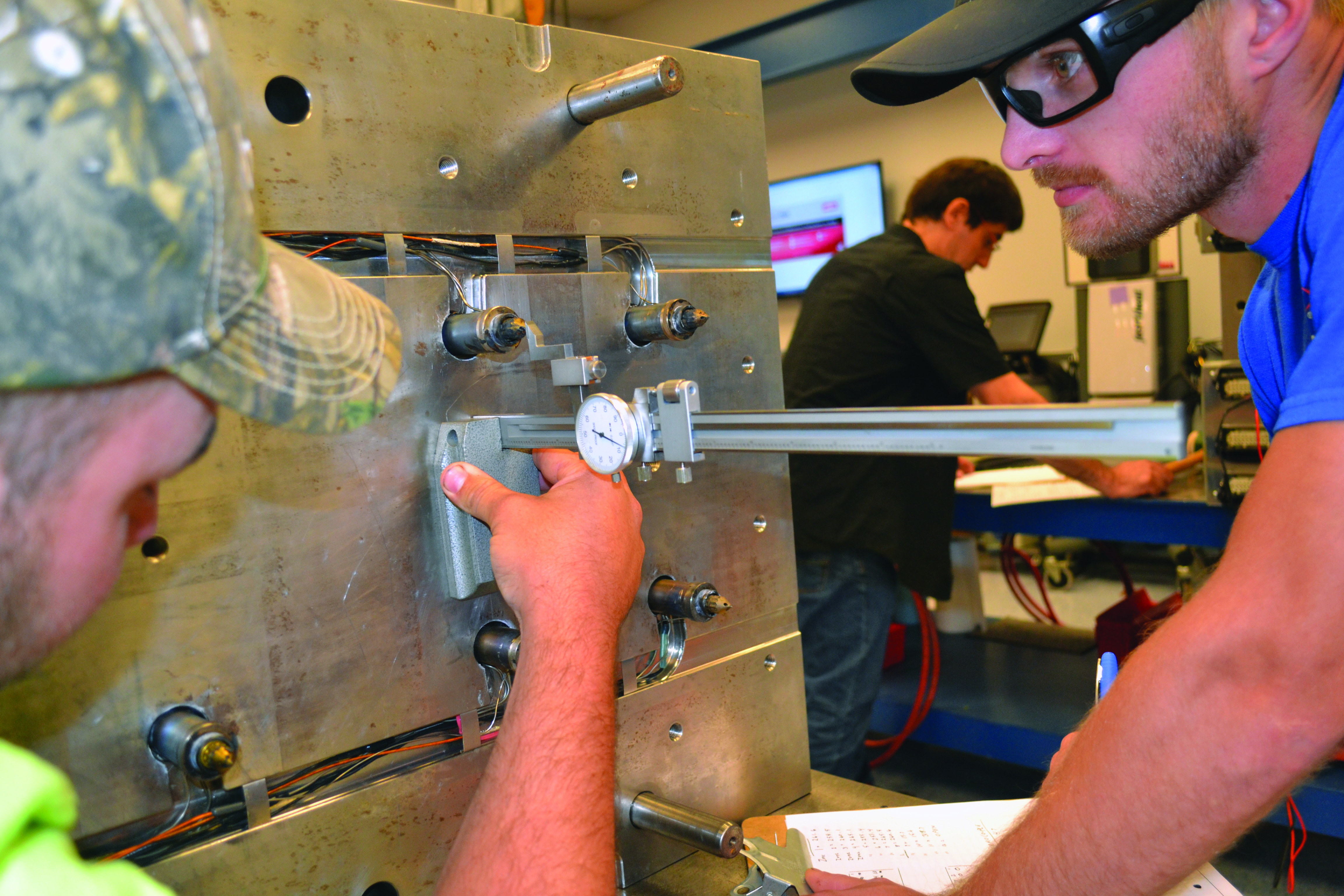
Breaking Down Hot Runner Maintenance (Figure 2). When using a fixed gate system (where there are no valve pins), remove the “A” cavity plate before removing the rear clamp plate to expose the nozzle tips, and measure and record the distance from the nozzle tip to the nozzle plate. Images courtesy of MoldTrax Maintenance Solutions.
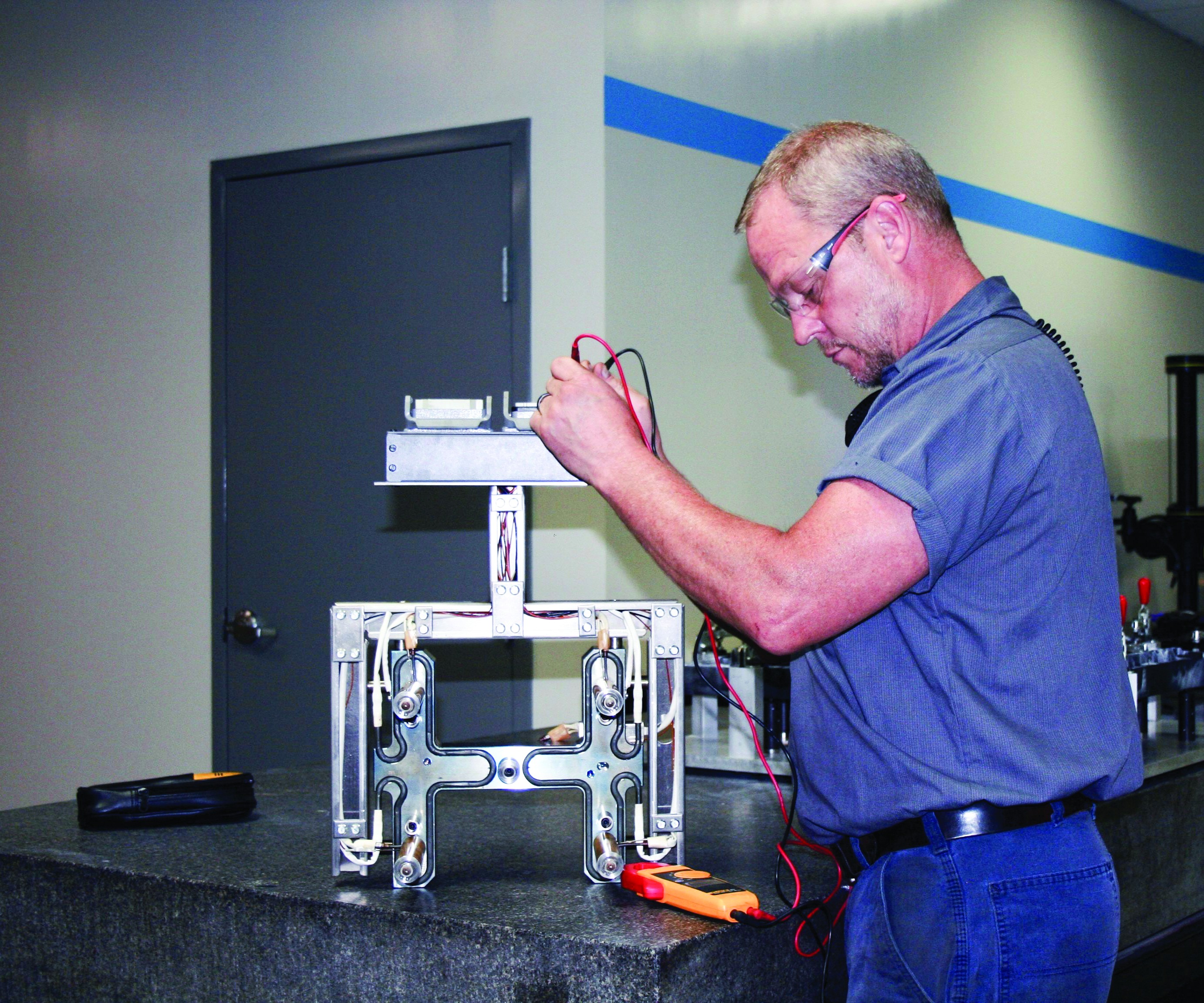
New Techniques Prove Benefits of Proactive Hot Runner Care (Breaking Down Hot Runner Maintenance Sidebar). The Millennium Tool Inc. team learned how to use the ohmmeter to monitor the hot runner systems and chart the resistance levels so that they can proactively repair or replace these components before there’s a larger problem. Image courtesy of Millennium Tool Inc.
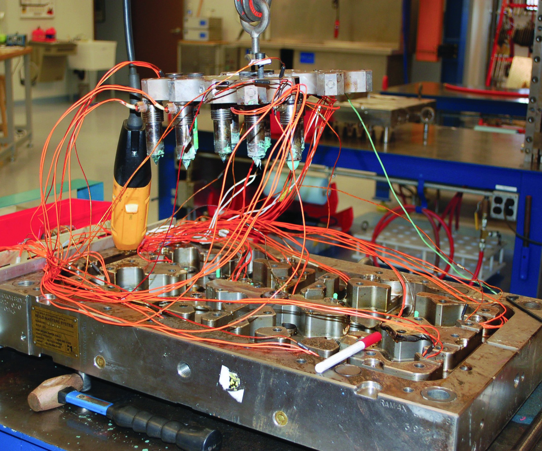
Breaking Down Hot Runner Maintenance (Figure 3). Removing a manifold may require extra force to break the plastic connection between the nozzles and the manifold feed channels, if the nozzles are bolted to the manifold plate. If the nozzles are not bolted to the nozzle plate, they may remain attached to the manifold, as shown here. Images courtesy of MoldTrax Maintenance Solutions.
Breaking Down Hot Runner Maintenance (Figure 4). Use a standard torque setting for the bolt size and a balanced, corner-to-corner pattern to torque manifold bolts if the manufacturer specifications are not available. Images courtesy of MoldTrax Maintenance Solutions.
Switch to Hot Runners Pays Off for Pulley Molder (Image 1). Osco’s Multi-Gate Nozzle specified by Retlaw offers balanced feed to each gate and minimal residence time within the hot runner. Images courtesy Retlaw Industries.
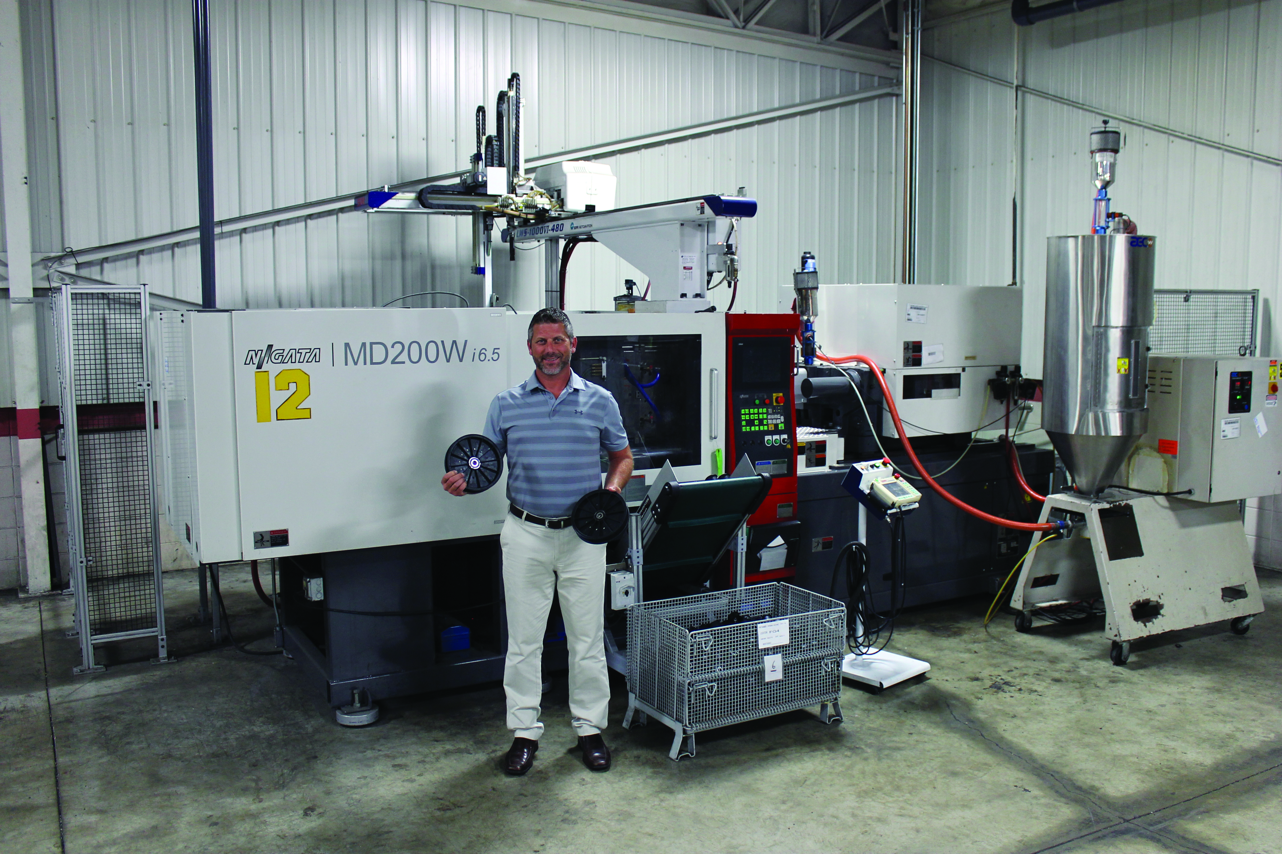
Switch to Hot Runners Pays Off for Pulley Molder (Image 2). CEO Mark Eberhardt says that Retlaw inserts mold pulleys in fully-automated molding cells, such as the one shown here. Images courtesy Retlaw Industries.
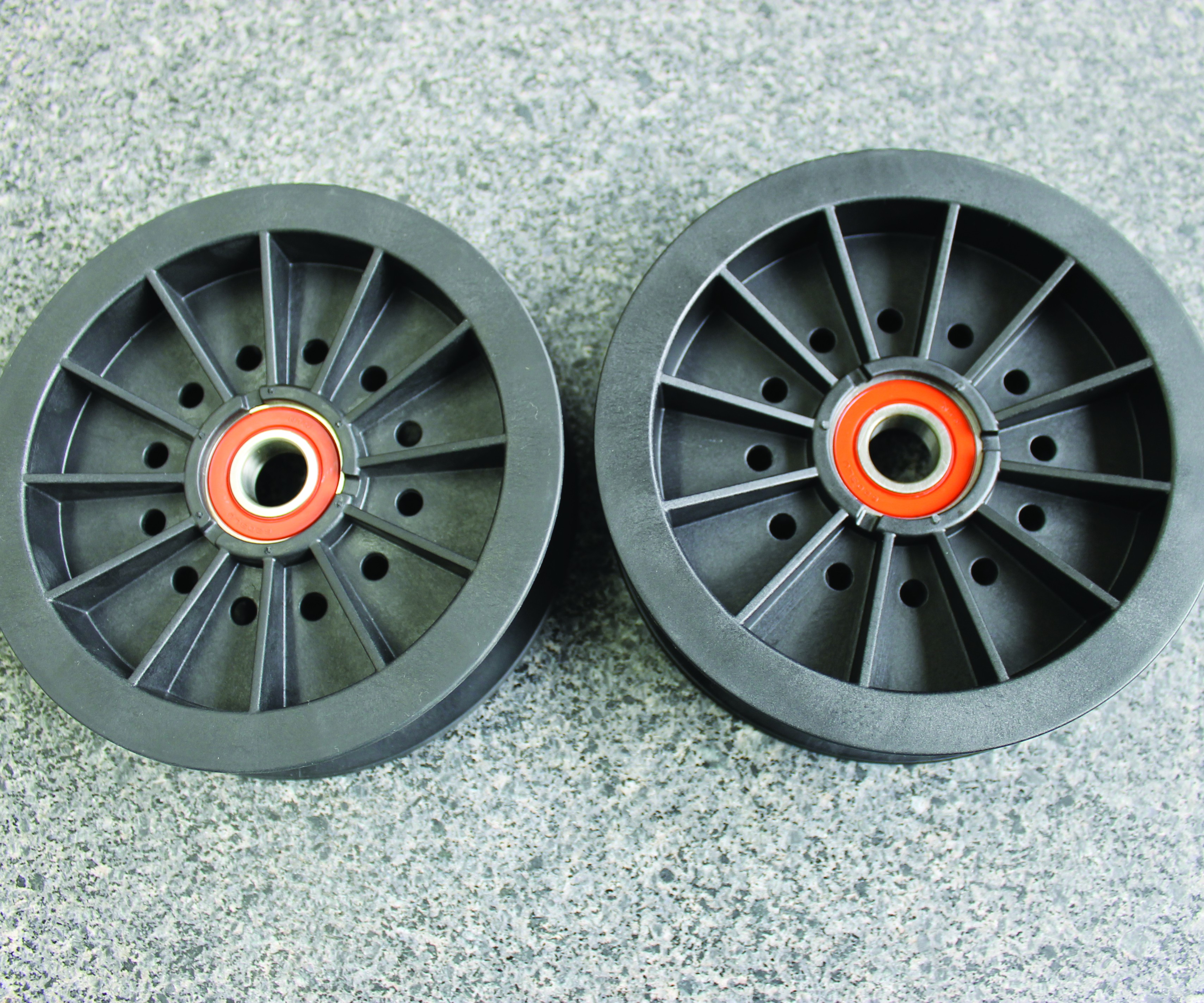
Switch to Hot Runners Pays Off for Pulley Molder (Image 3). Retlaw says pulleys molded utilizing Osco’s three-drop hot-runner system (photo right) have better surface finish and are more dimensionally stable than pulleys molded using a prior six-drop cold runner system. Images courtesy Retlaw Industries.


From the Editors: Be Proactive, Not Reactive
Successfully selecting, integrating and maintaining hot runner systems demands proactive involvement from original equipment manufacturers, molders and mold builders.
Hot runner systems are not new, but their use in toolrooms across original equipment manufacturers (OEMs), molding and mold building facilities grows every year as the technology behind these systems reduces molding costs and improves design capabilities. Cost reduction comes from advancements in venting, valve-gating, nozzle design, serviceability, temperature control, monitoring, melt delivery and maintenance and repair.


The whole mold supply chain can benefit from the right hot runner system. OEMs get better part quality and fewer part failures. Molders get faster cycles, less resin waste and decreased energy consumption. Moldmakers, many of whom are adding presses for sampling and production, get higher productivity from their molds. These benefits make the matter of better educating mold designers, moldmakers, molders, maintenance technicians and mold owners on hot runner system selection, integration and maintenance essential.
Therefore, MoldMaking Technology and Plastics Technology magazines have collaborated to bring you this special hot runner supplement. When developing the content, we set out to find answers to common hot runner system challenges that our readers share with us.
When it comes to design and engineering, for example, molders and mold builders encounter problems with the balance between drops, especially on high-cavitation molds that have smaller, tight-tolerance parts. Some attempt to artificially correct the problem with temperature variation between zones, which is not an ideal solution. Other shops struggle with determining the proper type of gate or determining how to cool the temperature near the tips.
When it comes to maintenance, the mechanical nature of these systems becomes a real challenge. Technicians need proper training to keep these molds in good shape and to execute repairs when the systems wear out or break. For example, many molders and mold builders fail to identify the root cause of degradation and contamination in the manifold.
As a result of these needs, we decided against presenting articles on the latest in hot runner systems and components (some of which can be found in the products sections of MoldMaking Technology magazine and Plastics Technology magazine). Instead, we opted to highlight stories on making better system decisions, on improving hot runner integration and on keeping those systems up and running.
The real lesson in all of this is getting every-one involved early—the hot runner system supplier, the moldmaker, the molder and the end customer. Everyone suffers the impact of bad decisions about any part of the melt delivery system, and that suffering can last for years.
About the Editors


Jim Callari
Jim Callari is the editorial director and associate publisher of Plastics Technology magazine.
Six Key Factors for Evaluating a Hot Runner System
Details matter when it comes to selecting and integrating a hot runner system. This guide makes that process easier by covering those details thoroughly.
Mold builders and injection molders have different requirements when it comes to hot runner systems. Mold builders are often concerned about price, delivery and quality, while the molder is concerned with operation, performance and ease of maintenance. However, both moldmaker and molder must be part of the decision-making process when considering a hot runner system and supplier to guarantee the best selection from available system options and to optimize integration of the system into the mold.
Here are six important items to consider when evaluating a hot runner system:
1. Manifold heaters. For installation, most manufacturers use a press. If the heater contact with the manifold is not uniform, there will be hot spots created in the heater element, which causes premature failure and non-uniform heating of the manifold itself. Also, process capability can be affected especially with some engineering materials, as their viscosity may be more temperature sensitive than commodity resins like polypropylene and polyethylene.
2. Nozzle heaters. Measuring the ohm resistance for each nozzle heater can provide good information when troubleshooting the hot runner system. Too great a variance may prevent uniform temperature profiles and the potential for process variation will increase. Additionally, the life of a heater with less efficiency is reduced because of the required increase in workload.
3. Nozzle tip orifice. Pressure differences in plastic injection molding are defined in the Hagen Poiseuille equation, where (Q) is the flow rate, (l) is the runner length, (n) is the material viscosity and (r) is the radius of the flow channel: ∆P=(8Qln)/(πr4)
The equation shows that any slight difference in “r” value, which includes the orifice in a hot runner nozzle and gate tip, is affected to a magnitude of the fourth power. This means that a small change in radius will result in a rather large difference in pressure drop from gate tip to gate tip. The common perception is that if the gate tips are all within tolerance, this will not matter. However, it is important to ask what the acceptable tolerance is along with the gate tip dimensions. Just because they are within tolerance does not mean there will not be a difference in pressure drop.
For example, a tolerance of +/- 0.002 inches on a gate diameter of 0.300 inches may be too large of a tolerance range to achieve consistent molding. Of course, a processor may adjust individual tip temperatures to try overcoming some of these variations. It is
important to understand that by doing this, the processor is changing the material conditions from which the parts are being molded. If the processor runs semi-crystalline materials, then he or she may create further issues with crystallinity differences near the gate versus other areas of the part.
Additionally, the resultant variations in thermal expansion of nozzle and manifold steel that occur because of different temperature settings could ultimately lead to other filling variations, leaking or breakage issues. For example, if a cavity is filling behind other cavities, a processor may increase the temperature of the nozzle feeding that cavity. However, that temperature increase could drive the gate tip further into the gate orifice because of additional thermal expansion. This reduces the effective radius (r), ultimately restricts the flow and counteracts the intent of the temperature increase (see Figures 1ab).
It is also important to understand that raising local nozzle or manifold temperatures may cause an increase in cycle time since the material and mold in that region will stay hotter for a longer period.
4. Stack height. It is important to check the uniformity of the stack height across all nozzle tips (see Figure 2). If these dimensions vary, then the engagement with the gate will also vary, and these variances could affect process capability because of resulting differences in channel geometry. Ask for the inspection report and consult the manifold supplier for an acceptable tolerance. Revisit the pressure drop equation to see if the tolerance that the supplier provides is acceptable for a given process and set of parts.
5. Flow channels. All gun drill manufacturers will claim variances of 0.001 inch per inch of travel. Check that they can verify that the cross drilling of the flow channels does not leave a step at the intersection of the cross-drilled runners. Refer to the earlier equation again. Check that the gun drill manufacturer scoped and honed the channels. Variations in flow channels could create differences in pressure drop through the regions of a manifold. Again, this refers to the portion of the equation involving the radius (r), which is raised to the fourth power.
Steps in the flow channel can create dead spots, which do not flush well when purging and cause color-change issues and material-degradation problems. Also, the steps make it possible for material to sit in the manifold for extended periods, which increases the likelihood for thermal degradation of the polymer.
The polymer’s natural flow path around the channel intersections also causes these dead areas. This happens even if the channel intersections are perfectly aligned (see Figure 3).
6. System cost. The cost of the system is often one of the most important things to consider, but relying solely on quotes from various suppliers is not the best way to approach the issue. Familiarity with the various options each hot runner supplier offers is helpful. For example, some suppliers may provide the ability to separate the manifold from the mold while the mold is still in the molding machine, reducing maintenance and downtime. Another thing to think about is how the channels are manufactured. The manufacturing method may affect color changes and require additional clean-out procedures that expand on traditional purging approaches. (See the sidebar for a list of common direct and indirect costs when evaluating the overall system.)
It is often said that the devil is in the details, and this certainly applies to hot runner system evaluation and performance. Issues arise, so it is important to be aware of some common challenges and potential sources of variation, including high pressures at assembly points, co-existence with a cold mold and platens, gating issues (cooling, clogging, drooling, stringing), processor skill level, shot size, residence time, leaking (see Figure 4), valve pin seating, shear flow imbalances, power consumption and thermocouple placement and contact.
Making a more informed decision requires a thorough understanding of the hot runner system’s design, manufacturing process and available options. It also requires a solid understanding of troubleshooting and mold qualification standards. Staying on top of the items described in this article will reduce downtime, improve part quality and decrease overall costs.
About the Contributors
David Hoffman and John Blundy
David Hoffman is a senior instructor and development manager for plastics education and training for the American Injection Molding Institute (AIM). John Blundy also contributed to this piece when he served as vice president of business development at Beaumont Technologies, Inc..
Breaking Down Hot Runner Maintenance
Improving a manifold’s maintenance plan requires specific skills and knowledge of its functioning areas.
Working on hot runner manifolds requires certain skills and training because of the heat expansion of the steel plates and components. If the mold and repair technician does not understand and cannot account for these effects, he or she may have trouble with mechanics, safety and effective processing. Developing a better maintenance plan for manifold service or repair requires a general knowledge of hot runner systems. That knowledge includes things like the system’s components (fixed or valve gates, heaters, thermocouples, wiring paths), maintenance history, complexity level and required maintenance skills. More importantly, proper manifold maintenance depends upon an understanding of its critical functioning areas (flow paths, seal areas, cooling channels) and its dimensional relationship with the cavities (gates and nozzle tips).
The first step when working on any manifold is identifying the goal of the work, which determines and verifies the specific maintenance plan. For example, is it routine preventive maintenance, or a new or repetitive problem with a mold or part? When it comes to manifolds, the more specific question may be, is preventive maintenance done at an appropriate cycle count? Or, does the PM cycle frequency need adjustment?
Once the shop sets a goal and strategizes a maintenance plan, there are general preparation, disassembly and re-assembly steps to follow for proper hot runner maintenance. These steps are general guidelines when working on most systems. Always check with your hot runner supplier for their recommendations on the proper techniques and sequences.
Preparation Guidelines
- Go to the crib and verify that the necessary tooling is in-house to support the maintenance plan. Necessary tooling includes heaters, thermocouples, nozzles, nozzle tips, valve pins and valve pin bushings.
- Confirm the estimated downtime with the production/molding department.
- Review past maintenance history to determine the most efficient method for mold and manifold disassembly. Most manifolds are removed from the manifold retaining plate in the horizontal position for safety and efficiency, but some are removed more easily in the standing or the vertical position.
- Determine a proper removal procedure for the electrical control box (for example, with nozzle heater and thermocouple wires connected or individually disconnected) and the best disconnection method for the manifold heater wires (for example, disconnected from the manifold or from the control box).
- Identify critical areas and special tools that may be necessary for disassembly. Examples include wooden spacer blocks to carry the manifold weight and to avoid damage to protruding nozzles, rubber caps to protect nozzle tips during manifold removal, eyebolts versus jack screws, a hand lift versus an overhead hoist and a technician’s hands versus a slap hammer for valve pin removal.
- Check all heaters and thermocouples for resistance and shorts using an ohmmeter before disassembly, then record the readings. To do this faster, use a portable hot runner mold testing system, such as the Mold Checker from Fast Heat, which tests hot runner manifolds to ensure that resistances of all thermocouples and heaters are within range.
- Map the position of each thermocouple and heater to verify their connection to the correct pin on the electrical connectors. Record the results (see Figure 1).
Disassembly Guidelines
- Remove the “A” cavity plate in a fixed gate system (no valve pins) to expose the nozzle tips before removing the rear clamp plate. Then measure and record the distance from the nozzle tip to the nozzle plate (see Figure 2). This dimension is critical to the relationship between the gate area and the land area and can be the root cause of parts that suffer long gate issues (like a spike of plastic sticking out from the gate location). This dimension also serves as a reference point to ensure that the nozzles are positioned correctly after the mold is reassembled.
- Ground the electrical controller directly to the mold, if using a controller to check the heater and thermocouples and if using wooden spacer blocks. The blocks will prevent the mold from being grounded through the steel bench, creating a shocking situation.
- Warm up nozzles to 250°–350°F (depending on the resin) when removing the pins from a valve-gate system. This eases the extraction of the valve pins from the manifold system which prevents the resistance of cold plastic that can damage the valve pins.
- Move the valve pins back or to the open position while they are warm. This prevents damage to the tips on delicate valve pins and protects them if the cavity plate gets jammed on the leader pins and does not come off evenly during its removal.
- Number every tip to a home position for accurate reassembly, so the valve pins take a seat (or running fit) in their related valve pin bushing during production.
- Handle valve pins carefully when removing them, placing them on a bench or in a cleaning basket when cleaning and drying them and when returning to the bench and reinstalling them into the mold. Careless handling will create dings or bend the fragile tips.
- Take additional reference measurements from the manifold plate to the manifold or to any expansion spacers located at the top of the manifold before removing any bolts that are securing the manifold. These measurements help verify that everything was put back together correctly. Measure closest to the corners of the manifold to determine the flatness of the manifold in relation to the manifold plate. If one or more corners varies by 0.010 inch or more, it is likely that the manifold does not sit flat on the nozzles, which points to a potential tooling stack problem.
- Clean and stone an area before taking any measurements. This helps ensure more accurate readings.
- Measure from the top of the bridge to the manifold plate and down to the manifold when a manifold bridge is part of the system. This measurement is useful during reassembly.
- Note wiring routes through the plates and use wire labels to identify the correct heater and thermocouple positions.
- Remove the manifold bolts and carefully lift out the manifold once all the measurements are taken and all the wire clips are removed. If the nozzles are bolted to the manifold plate, removing the manifold might require extra force to break the plastic connection between the nozzles and the manifold feed channels.
- Document this procedure with images, as damage can occur if prybars are jammed in the wrong area. If the nozzles are not bolted to the nozzle plate, they may remain attached to the manifold (see Figure 3). At this stage, use extreme caution to ensure the nozzles are not bumped or broken, damaging the tips. Some technicians prefer to pull the manifold while it is hot, which helps to break the nozzle/manifold connection. Wear proper gloves and other appropriate gear when using this method.
- Clean all tooling carefully. Do not haphazardly pile valve pins and other delicate components into a single steel cleaning basket.
- Make sure there is no plastic or residue at the sealing points located at the junction of the plastic flow paths.
Re-assembly Guidelines
- Be careful using soft brass, aluminum or copper tools during reassembly, as they easily flake or chip. These chips can fall into areas that cause sealing problems and slow leaks.
- Use the right tool for the right job to avoid excessive force for reinstalling the tooling. Stop and identify the cause of any resistance before breaking out the big hammer.
- Work methodically during reassembly. Do not forget to install bolts, dowels and spacers, as this will require the manifold to be disassembled again. Remember that manifolds fail because of the way we put them together, not because of the way we take them apart.
- Read the feedback from your hands and tools. For example, some root causes of manifold leaks include nozzles that fit tightly into bores, manifolds that rock (or do not sit flatly) after being reset onto nozzles and dowel pins that are not properly lined up or engaged.
- Torque the manifold bolts to manufacturer specifications. If those are not available, then use standard torque settings for the bolt sizes in question. Use a balanced, corner-to-corner pattern if a manufacturing torque pattern is not available (see Figure 4).
- Use an anti-seize product on the bolt threads and under the head to prevent waste in torque force. Technicians often waste as much as 30 percent of torque force to overcome friction.
- Re-heat nozzles to ease installation if installing valve pins.
- Test manifolds, nozzle heaters and thermocouples with an ohmmeter or a portable hot runner mold testing system before bolting it onto the back-clamp plate.
- Recheck heaters and thermocouples for shorts and connectivity issues after the clamp plate is reinstalled and tightened, and then document the readings.
- Make sure there is no variation in temperature between the cavity plate and the nozzle plate when installing a cavity plate to a nozzle plate or working on manifolds in the press while changing or cleaning nozzle tips. For example, a 25-degree difference in temperature could cause the center-line distance of the nozzles to be off by 0.004 inch over 24 inches in relation to the cavities, resulting in misalignment between the cavities and nozzle seals. This will damage the seals and cause slow, catastrophic plastic leaks.
- Document all issues throughout maintenance, such as poor wiring conditions, wire pinch points, worn electrical connectors, stripped threads and damaged electrical boxes. Take pictures along the way for future reference.
- Create and use maintenance manuals to advance the team’s knowledge base about the most appropriate, efficient and safest methods to use when working on a specific manifold system.
Although working on hot manifolds is an area of mold maintenance that requires a
bit more knowledge, focus, patience and hand skills, these general preparation, disassembly and re-assembly guidelines will help structure and simplify a hot runner maintenance plan. The key is being proactive, creating a data-driven shop environment and encouraging continuous improvement across the toolroom.
About the Contributor
Steve Johnson
Steve Johnson is the president of MoldTrax, which provides specialized course work, hands-on bench training, maintenance software, maintenance products, toolroom design and maintenance efficiency auditing.
Switch to Hot Runners Pays Off for Pulley Molder
Retlaw has cut scrap, improved part quality and slashed cycles since adopting hot runner technology.
Change never comes easily in manufacturing, and injection molding is no different. Retlaw Industries got along fine without hot runners in its 40-year history, so why would the company bother changing? After all, if it’s not broken, why fix it?
Retlaw Industries is based in Hartland, Wisconsin. Retlaw started in 1977 as a tool shop making molds. Then it added a press to sample molds. “By 1982, we were asking our customers, ‘Why don’t we just mold your products too?’” says Mark Eberhardt, CEO and sole owner of the family-owned group. Today, moldmaking is a small part of the company’s business.
Retlaw operates out of a 50,000 square-foot plant, employs about 40 people and runs 20 injection molding machines ranging in size from 50-720 tons clamping force. Its business is split evenly between custom jobs and a proprietary product line of 33 percent glass-filled nylon pulleys that it sells directly to original equipment manufacturers (OEMs) of lawn and garden equipment, conveyors, fitness equipment and manufacturers in a range of other industries.
Until this past spring, Retlaw could not justify utilizing hot runners on its pulley line. Eberhardt says, “Initially the volume wasn’t there. The sales weren’t there, so it didn’t make sense for us to invest in a hot-runner system. But as that changed, so did our philosophy on manufacturing the part and the best way to mold the part.”
Retlaw started to look more seriously at hot runner technology about two years ago. The company started working with Osco Inc. of Rochester Hills, Michigan. Retlaw engineers and Peter Rebholz, Osco’s vice president of sales, noticed something troubling on a three-plate, four-cavity mold running small-diameter pulleys. It was eye-opening. “The runner was a pretty substantial percentage of the overall shot weight,” Rebholz says. He meant that this application was ideal for going runnerless. Eberhardt says, “The parts were getting smaller, the volumes were getting higher and we were generating a higher percentage of regrind than we were comfortable putting back into the process. We were generating a lot of regrind and dust, which translated into increased maintenance on grinders and dryers. We really wanted to get rid of the mess and the cost associated with it.”
To address this problem, Retlaw and Osco worked together to retrofit a single-cavity mold with the latter’s Multi-Gate Nozzle (MGN) technology. The pulleys had six gating points on the three-plate tool. Peter Rebholz says, “In initial discussions with Retlaw’s engineering team, the team said it wanted six points of injection on the hot runner system. That’s perfectly logical. I thought we would be able to produce a well-balanced part with only three gates, which will also keep the expense down. As it turned out, three injection points gave everything to Retlaw that it wanted. So, when we went into the multi-cavity tool, we were able to keep the hot runner cost down and the controller cost down.”
Osco’s MGN provides a balanced feed to each gate and minimal residence time within the hot runner. Offering temperature control at multiple gates, MGN has been shown to be effective especially when molding “round parts that need to stay round,” Rebholz says. For Retlaw, the MGN is furnished with carbide tips. This is important because glass-filled nylon tends to run hot, and it tends to be abrasive.
In its collaboration with Osco, Retlaw’s next step was to build an entirely new tool around the hot-runner technology. The tool is equipped with inserts, which enable the pulleys to be molded in a variety of sizes, diameters, wall thickness and configurations. Eberhardt says that since making the shift to hot runners, Retlaw has noticed a 6 percent improvement in molding cycles and better part quality. What’s more, he says, “we don’t run the granulator anymore because there’s nothing to regrind.” The molder used to run pulleys on 310-ton presses because of the size of the tool. Now, it molds the same parts on 200-ton presses, which saves energy.
What’s next for Retlaw and hot runners? “Our goal is to take all existing tooling for our line of pulleys and retrofit them to accommodate hot runners,” Eberhardt says. “If we find that retrofitting is not possible, then we will build new tooling as we move forward to
accommodate hot-runner technology.”
About the Author
Jim Callari
Jim Callari is the editorial director and associate publisher of Plastics Technology magazine.


Related Content

The Trifecta of Competitive Toolmaking
Process, technology and people form the foundations of the business philosophy in place at Eifel Mold & Engineering.
Read More
Making Quick and Easy Kaizen Work for Your Shop
Within each person is unlimited creative potential to improve shop operations.
Read More
Leading Mold Manufacturers Share Best Practices for Improving Efficiency
Precise Tooling Solutions, X-Cell Tool and Mold, M&M Tool and Mold, Ameritech Die & Mold, and Cavalier Tool & Manufacturing, sit down for a fast-paced Q&A focused on strategies for improving efficiencies across their operations.
Read More
MMT Chats: Marketing’s Impact on Mold Manufacturing
Kelly Kasner, Director of Sales and Marketing for Michiana Global Mold (MGM) talks about the benefits her marketing and advertising, MGM’s China partnership and the next-generation skills gap. This episode is brought to you by ISCAR with New Ideas for Machining Intelligently.
Read MoreRead Next

How to Use Continuing Education to Remain Competitive in Moldmaking
Continued training helps moldmakers make tooling decisions and properly use the latest cutting tool to efficiently machine high-quality molds.
Read More
How to Use Strategic Planning Tools, Data to Manage the Human Side of Business
Q&A with Marion Wells, MMT EAB member and founder of Human Asset Management.
Read More
Are You a Moldmaker Considering 3D Printing? Consider the 3D Printing Workshop at NPE2024
Presentations will cover 3D printing for mold tooling, material innovation, product development, bridge production and full-scale, high-volume additive manufacturing.
Read More