Simplify Mold Machining
Use true five-axis simultaneous machining for your molds and inserts.
In the specialized world of mold and insert manufacturing, there are several benefits to employing five-axis machining. For example, five-axis machining adds two more axes of rotation that allows the cutter head to move into positions not accessible with a standard three-axis CNC machine. Additional benefits include the ability to use shorter tools and multiple machine orientations in one setup. This simply gives you more cutter (tool) positions from which to access more of the part you are cutting.
The most routinely used technique for five-axis machining is 3+2. Here, the operator locks one of the advanced axes in a set position and then machines with a traditional three-axis tool path. However, mold machining can truly benefit from using true five-axis simultaneous machining, where all axes of motion move at the same time. Following are four common areas of mold machining that can reap the benefits of true five-axis simultaneous machining.
Tool positioning. When machining molds, positioning the cutter has major impact on the manufacturing process in terms of the goals that must be met, including employing the fewest number of tools, using the shortest possible tooling and ensuring toolholder clearance.
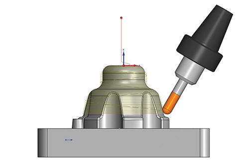
Five-axis simultaneous machining helps minimize the overall number of tools used to machine a mold by enabling one tool to machine more of the part. This is a major advantage over a fixed orientation such as 3+2 where the programmer must define a tool that is long enough to machine all surfaces from that orientation. To maintain efficiency, a good programmer must select several tools when the depth-to-diameter ratio is larger than 4-to-1. In contrast, employing a dynamic tilting strategy in a single tool path allows the software to tilt the tool and holder away from the part to avoid gouging and collisions. The result is a single short tool with the ability to machine all the surfaces contiguously in a single tool path.
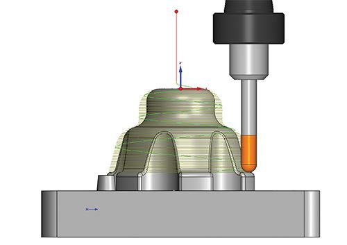
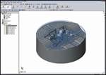
For example, an insert that is 4 inches long would be machined using a 0.375-inch ball mill. Figure 1 shows the result of using 3+2, which includes five separate tool paths using five different orientations, to completely machine the insert. Figure 2 shows a single five-axis simultaneous tool path working a spiral strategy to machine the insert.
Surface finish is always a large concern for moldmakers, and there is usually some degree of hand polishing to be done after machining is complete. The goal when machining a mold or insert is to limit or remove secondary polishing operations. The first example shows tool paths overlapping each other, which can require hand polishing to remove any marks caused by this overlapping. The full five-axis tool path will be continuous, without any overlapping paths, yielding a much smoother surface finish.
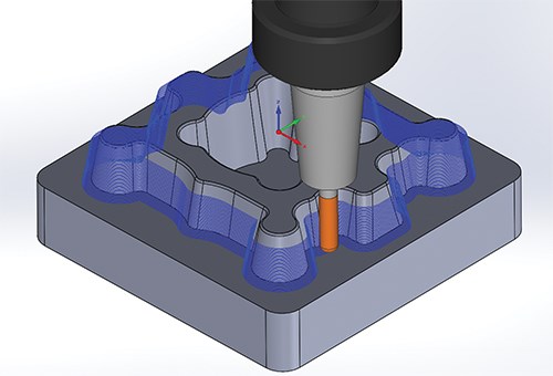
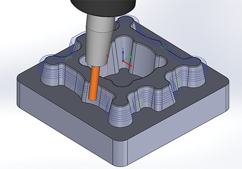
Tapered tools and swarf cutting. Also common in mold machining is the use of tapered tools to match a part’s draft angles. For example, there are two methods to machine a mold designed with a two-degree taper. The first method employs a ball mill following a 3D tool path that generates the surface with small step-overs. The second method uses a two-degree taper cutter that machines an entire surface, or batch of surfaces, in a single path.
With five-axis simultaneous machining, you can use a swarf cutting strategy in which the tool is automatically tilted in the tool path so that its side is aligned to the surface. This allows a traditional non-tapered end mill to emulate any number of tapered cutters. Figure 3 shows a traditional 3D tool path used to machine tapered surfaces, while Figure 4 shows the use of five-axis simultaneous swarf cutting to machine the group of surfaces in three passes.
Three-to-five-axis conversion. The most common mold machining technique using simultaneous five-axis milling is three-to-five-axis conversion. In this technique, a robust three-axis engine generates the tool paths and then applies tilting to the three-axis tool path. This avoids gouging of the holder and arbor, and generates smooth, precise, gouge-free five-axis tool paths using short tools.
Figures 1 and 2 depict the three- to five-axis conversion. Notice that the tool length needed to approach the same area is much higher in the conventional three-axis tool path than in the five-axis tool path. This much smaller length results in more stable cutting that provides excellent surface quality.
Avoiding multiple setups. With simultaneous five-axis machining, the entire core/cavity/insert can be completed in a single setup. The piece does not have to be removed for re-positioning when machining pockets for slider seating or drilling cooling holes, for example, as it would with three-axis machining.
The improved surface finish quality, fewer number of necessary tools, diminished cycle times and reduced operations achievable with five-axis machining give it a clear advantage over standard three-axis machining, the use of tapered tools and locked advanced-axis machining.
Related Content
Plastic Prototypes Using Silicone Rubber Molds
How-to, step-by-step instructions that take you from making the master pattern to making the mold and casting the plastic parts.
Read MoreLaser Welding Versus Micro Welding
The latest battle in finely detailed restoration/repair of mold materials.
Read MoreMaintaining a Wire EDM Machine
To achieve the ultimate capability and level of productivity from your wire EDM on a consistent, repeatable and reliable basis, regular maintenance is a required task.
Read MoreFundamentals of Designing the Optimal Cooling System
The right mold components can help improve mold cooling and thereby produce higher-quality parts.
Read MoreRead Next
Seamless Integration Between CAD and CAM Applications
How to avoid “walls” between mold design and manufacture.
Read MoreHow to Use Continuing Education to Remain Competitive in Moldmaking
Continued training helps moldmakers make tooling decisions and properly use the latest cutting tool to efficiently machine high-quality molds.
Read MoreReasons to Use Fiber Lasers for Mold Cleaning
Fiber lasers offer a simplicity, speed, control and portability, minimizing mold cleaning risks.
Read More
