


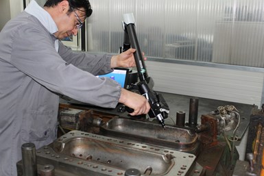
Glass-bottle mold manufacturer Omega Enterprises of Winchester, Indiana, uses a combination of structured-light scanning technology and CAD/CAM software to build and repair molds. Before implementing the scanner, the company altered molds and blanks with multiple compound angles by hand, which increased costs. Photo Credit: Hexagon Manufacturing Intelligence
Nowhere is the connection between production and creativity more evident than in reverse engineering, which challenges manufacturers to find new ways to recreate or improve upon existing products instead of starting from square one.
Data Collection and System Interoperability
Increasingly sophisticated engineering and production tools have propelled the development of equally complex products that are challenging to reverse engineer. Data collection for reverse engineering entails measuring an object with a coordinate measuring machine (CMM) equipped with 3D-scanning technology, a portable piece of metrology equipment or a structured white light digitizer, to name a few options.


Many major manufacturers of injection-molded parts have standardized the use of computed tomography (CT) measurement, as it’s ideal for comprehensively scanning complex parts with undercuts and geometries that cannot be accessed with probes or “seen” by scanners. CT scanning is an ideal option for objects with shiny surfaces, organic shapes, miniaturized geometries that are tough to measure with tactile probes and inner structures such as 3D-printed lattices that can’t be measured with optical scanners.
Because such a wide range of metrology technologies are available, the requirements of specific applications should be considered, including part tolerances and features such as relief patterns, cast holes and edges. Access is an additional factor, as probes can reach areas out of the line-of-sight of laser scanners, while scanners may be unable to access tight areas due to head size and short reach. Variables such as accuracy, speed, ease of use, required data density and the measurement environment should also be considered.
Usually represented as a point cloud, measurement data is typically processed into a standard triangle language (STL) mesh file and modeled into a usable format, such as a set of non-uniform rational basis spline (NURBS) surfaces, or a solid CAD model. Plug-and-play solutions that seamlessly connect metrology equipment to CAD, CAE and CAM systems help ensure high-quality data transmission. In this scenario, objects appear in real time as they’re scanned and can be moved seamlessly between various applications that contribute to the end result.
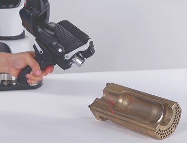
This laser-stripe scanner, shown scanning a bottle mold for reverse engineering, offers high-speed 3D scanning without performance degradation on any surface. Its ultra-wide, horizontally oriented laser scan line and fully automatic exposure settings make 3D digitization faster and more accurate.
While point data can be imported into a CAD system, taking advantage of software developed specifically to work with point clouds and that offers reverse-engineering functions speeds up the process of generating high-quality models because they provide tools for repairing and improving meshes and creating and trimming surfaces and solids. The ability to control the quality of developed geometry and analyze deviations compared to a scan is a significant advantage of reverse-engineering software.
Solutions that offer reverse-engineering functionality and customize systems to fit specific needs enable designers to create models, simulate performance and program molds for production within a single environment. Once reverse engineering is complete, preventive analysis could be used within the same environment to detect potential manufacturing issues, such as welding lines and air traps, and determine the best gate location and other factors.
In addition to the convenience and speed of using multiple digital tools within one environment, a benefit of connecting point cloud data directly to a single system is that it negates the need for separate CAD, CAE and CAM solutions. This effectively cuts out the middleman and ensures that data isn’t lost in multiple translations to achieve a seamless transition between critical tasks.
The goal of the redesign, which entailed reverse engineering, was to simplify the injection mold, make it possible to produce the device as a one-piece product and ensure that the new mold tool did not include side actions or lifters.
Direct Modeling
Direct or dynamic modeling offers the ability to generate solid models without using parametric or history-based modeling and is one of the most powerful tools available for reverse engineering. Flexibility is at the core of this technology. It allows engineers to manipulate digital models quickly and intuitively using various approaches based upon personal preference and proven efficiency.
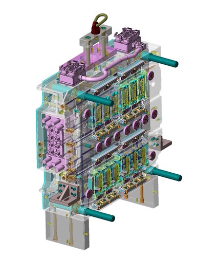
Built-in reverse-engineering tools can help analyze core and cavity separation in plastic injection molds such as this one. These specialized tools can be used to identify and isolate undercuts, or to compare geometry that’s been reconstructed with original point clouds.
Dynamic modeling delivers the ability to easily manipulate surface, mesh, wire and solid models interchangeably for a high degree of agility during the design process. On the other hand, history-based modeling employs a feature tree of operations digitally built from the ground up, limiting designers to follow a step-by-step approach. This approach could work perfectly, at least until the designer realizes at operation No. 526 that they missed a step at operation No. 5 and may subsequently break the tree in their attempt to rebuild it. Direct modelers also have the significant advantage of working with data from other CAD systems, as reverse engineering jobs often need to address only a part of a model, keeping the rest untouched.
Combining Technologies
Combining metrology technologies and flexible modeling tools is especially useful for prototyping applications involving existing CAD models and newly scanned data so that entire components don’t need to be reverse engineered to build molds. In cases where automotive OEM parts need to be adapted to fit a new vehicle model, a clay model made of the new part can be scanned to create a point cloud for import into a CAD or CAD/CAM system. Reverse-engineering software, or a CAD/CAM solution with advanced tools for reverse engineering and mold design, is helpful in this scenario because the software offers tools for handling the idiosyncrasies and challenges common to both.
For instance, if a mud flap developed for a new vehicle model features bolt holes in the same location as the previous model, but the shape of the new mud flap is completely different, the new and existing data can be combined to create a new model and, ultimately, a new mold. Dedicated reverse-engineering functions speed the process along by making it easy to clean point clouds, generate high-quality mesh surfaces, fill holes and bridge gaps to derive accurate, usable geometry.
Solutions that offer reverse-engineering functionality and the ability to customize systems to fit specific needs enable designers to create models, simulate performance and program molds for production within a single environment.
Manufacturability
Regardless of industry, a common application for reverse engineering is simply to make a product more manufacturable. While designs are often showcased as final products, those products may have to be prototyped and reverse engineered to ensure that they can be produced and address logistics such as draft angles and lifters for undercuts to support easy extraction.
A computer mouse, for example, may feature complex surface geometry and include a handful of components that come together to create the final product. Suppose the mouse cannot be manufactured as designed. In that case, it can be more productive to scan the prototype product to create new geometry, even if a CAD model is available, because the geometry required may be drastically different from that of the model provided. Direct import of point clouds into dedicated reverse-engineering software paves the way for dynamic wireframe grid construction and automatic surface creation, as well as automatic mesh creation, cleaning and smoothing.
Case in Point
Based in the United Kingdom, Fenton Precision Engineering (Wellingborough) redesigned an injection-mold tool that RBR Active (Cambridgeshire, U.K.) uses to manufacture a medical device that reduces the possibility of deep-vein thrombosis. RBR Active develops solutions for restricted blood flow. The goal of the redesign, which entailed reverse engineering, was to simplify the injection mold, make it possible to produce the device as a one-piece product and ensure that the new mold tool did not include side actions or lifters.
U.K.-based Fenton Precision Engineering redesigned an injection mold tool that RBR Active uses to manufacture a medical device that reduces the possibility of deep-vein thrombosis. Redesign entailed reverse engineering to simplify the injection mold and make it possible to produce the device as a one-piece product without using side actions or lifters.
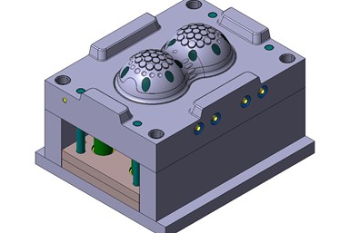
Using a CAD system with hybrid modeling and scan-data capabilities developed for reverse engineering, the company collected point data from its CMM to combine surfaces and solids and seamlessly work between them. A wall section at the top of two dome structures on the product, which contains 38 nodules, had to be thin to allow flexibility—but not too thin.
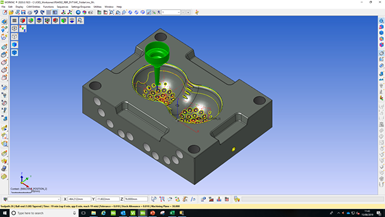
Fenton Precision Engineering used an integrated CAD/CAE application to simulate the filling phase of the injection-molding process to arrive at an ideal wall thickness. The software was used to define initial molding criteria and gating positions to achieve a balanced filling of the cavities under optimum manufacturing conditions.
To arrive at the ideal wall thickness, the company used an integrated CAD/CAE application to simulate the filling phase of the injection-molding process. The software was used to define initial molding criteria and gating positions to achieve a balanced filling of the cavities under optimum manufacturing conditions. The new tool was constructed around the product, and the result was an open-and-close mold with two cavity plates, support plates and backplates, comprising around 30 different components.
Dedicated reverse-engineering functions speed the process along by making it easy to clean cloud points, generate high-quality mesh surfaces, fill holes and bridge gaps to derive accurate, usable geometry.
Reverse engineering individual components that will ultimately be used in combination may be required when assemblies don’t come together seamlessly. This disconnect could be due to a design flaw or changes made in the original designs. CAD models can be used to pinpoint problem areas when one or more components need to be adapted to fit with another, and flexible modeling tools help with the process of melding existing, usable geometry with new data.
An operator scans a mold used to make steel components at Mectron s.r.l. Via dell’industria, based in Isola del Liri, Frosinone, Italy. As the original CAD model had been lost, scanning was the first step in creating a digital twin of the component and subsequently making changes to the original design.
Built-in reverse-engineering tools can help analyze core and cavity separation and align a part that’s been reverse engineered with another CAD model in the software. These tools are used to identify and isolate undercuts or to compare geometry that’s been reconstructed with original point clouds.
As an essential step in many manufacturing workflows, efficient reverse-engineering processes rely upon a multi-directional flow of data across digital systems, from data collection and modeling, through manufacturing. The increasing availability of advanced technologies that help engineers recreate or redesign existing products provides them with the tools they need to keep meeting the complex challenges of a continuously evolving industry.


Related Content

Laser Welding Versus Micro Welding
The latest battle in finely detailed restoration/repair of mold materials.
Read More
How to Use Diffusion Bonding to Optimize a Mold’s Thermal Performance
Joining dissimilar metals has tremendous potential for conformal cooling, but to successfully use diffusion bonding, a mold builder must understand the complexities of the interface and its effect on the chemical and thermo-mechanical properties of the bond.
Read More
Portable Low-Heat, Non-Arcing Resistance Welder for Mold Repair
Rocklin’s user-friendly MoldMender Micro Welder delivers simple and cost-effective localized repair in-house with precision and versatility, enhancing mold and die durability and reducing disassembly and downtime.
Read More
Surface Finish: Understanding Mold Surface Lingo
The correlation between the units of measure used to define mold surfaces is a commonly raised question. This article will lay these units of measure side by side in a conversion format so that companies can confidently understand with what they are dealing.
Read MoreRead Next

Combining Customized Software with CMM Reduces Production Bottleneck
In order to reduce downtime on its EDM and CNC machines when setting up new jobs, moldmaker Kavia Tooling turned to a coordinate measuring machine from Hexagon Manufacturing Intelligence to create an offline zero transfer system ahead of the manufacturing process for parts and electrodes.
Read More
Data-Driven Quality Control
Enhanced metrology technologies can help streamline mold scanning and inspection.
Read More
How to Use Continuing Education to Remain Competitive in Moldmaking
Continued training helps moldmakers make tooling decisions and properly use the latest cutting tool to efficiently machine high-quality molds.
Read More