
Seamless Integration Between CAD and CAM Applications
How to avoid “walls” between mold design and manufacture.


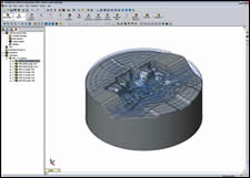
Photo 2: HSM toolpaths for roughing procedures in single window integration.
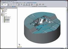
Photo 4: Finishing toolpaths for mold cavity
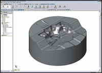
Photo 1: Design of a cavity for a plastic injection mold. Photos courtesy of SolidCAM.
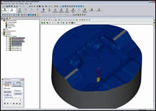
Photo 3: Simulation of roughing and presentation of rest material.
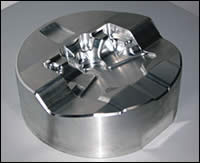
Photo 5: Finished cavity for plastic injection mold.
The May issue published an article,“Does Your CAD System Support Design and Validation in One Window?” and discussed the benefits of a 3-D CAD system supporting both design and validation “in one window.” CAD software that combines both processes in one system allows product engineers and mold designers to work more productively, and thus reduce costly errors. The imaginary “wall” known as data translation—which has stood as a barrier between product and mold designers—is now eliminated.
However, the majority of moldmakers generate revenue not by selling a 3-D file of a mold as an engineering service, but by delivering the final physical mold. Therefore it is important to also include the manufacturing process in the above considerations. How can we avoid “walls” between mold design and manufacturing and how can we achieve a seamless integration between the CAD and CAM applications?


Associative CAD/CAM Usage
The best way to avoid these walls is to build the CAD and CAM application on the same 3-D database. This avoids the process of translating data from one format to the other, which could delay the project and increase the risk of errors. It also enables associative CAD/CAM usage, where modifications in the CAD geometry will automatically update the corresponding CAM programming. By eliminating the communication gap between mold designer and NC programmer, the overall leadtime for a mold can be reduced. If the CAD and CAM applications have the same user interface—ideally via a single-window integration—a major improvement can be achieved: NC programmers on the shop floor can apply design-for-manufacturing operations in their own environment by editing the mold geometry as problems arise.
In principle, there are two ways to achieve these benefits:
1. The CAD/CAM software supplier develops its own “native” CAD application on the same 3-D database used for the CAM application.
The seamless integration is then possible; however, the investment to develop a complete CAD application may not be profitable, if the system supplier sells only several thousand CAD licenses per year. Also, it’s important to take into consideration that the supplier has to develop design-related functions—including analysis, PDM and geometry import capabilities, which moldmakers need to communicate with their customers.
2. Build a CAM application on the 3-D database of an existing mainstream 3-D CAD system.
Here, through single-window integration, all machining calculations are defined, calculated and verified in the same CAD environment. All geometries used for machining are fully associative with the mold design model. When the geometry of the mold design is modified, the CAM software enables the user to automatically synchronize all machining operations with the updated geometry. An important tool for associativity is a powerful assembly mechanism. Here an assembly top-down approach is used, where the core of all components is the part to be manufactured and all other components like molds or toolpaths should reference to it. The assembly mechanism can update all references, when changes are made to the original design. Also, vice versa, any mold adaptations performed on the shop floor in the CAM software can be easily used by the designer to update the original project assembly.
This approach does not only ensure an efficient and easy-to-use NC programming, but also a cost-effective one for the CAM software supplier: He can focus his development resources to the CAM modules, and can leverage the CAD partner for part and mold design, and related functions—including all of the geometrical interfaces, mold fill simulation and additional analysis tools.
Advanced CAM Functions—High-Speed Machining
By developing on a 3-D CAD mainstream platform, a CAM supplier can focus its resources 100 percent to support advanced manufacturing technologies. A good example is high-speed machining (HSM), which is becoming more widely adopted in many mold, tool and die shops to machine hardened steel cavities.
HSM machines enable the use of higher axis feedrates and also higher spindle speeds up to 60,000 rpm. Much less heat is transferred into the cutter tool and the working mold, which results in significantly higher material removal rates without degrading of part accuracy or quality. Finally, HSM reduces the leadtime of a mold and reduces expenses through greater reliability.
To support high-speed machining of complex 3-D shapes, the CAM engine must generate optimal roughing and finishing CNC toolpaths. You should look for software that includes several enhancements to its CAM technology that will make HSM operations possible, such as the following:
Avoiding Sharp Angles in the Toolpath
Each time there is a sharp angle or a sudden change of direction, the controller reduces the feedrate. This increases the machining time, marks the piece and wears out the tool. An enhanced HSM module will smooth the paths of cutting maneuvers and retract wherever possible to keep a more continuous machine tool motion.
Ensuring that the Tool Stays in Contact With the Part as Much as Possible
Each time the cutter lifts off the part and then returns to it, time is wasted. In addition, the actions increase wear on the tool because of the thermal shock caused by the repeated cooling and heating of the cutter. There also is an increased risk of tool breakage because of the changing load on the tool when it stops and starts cutting.
Optimizing Non-Machining Moves
Non-machining moves are not productive and should be eliminated wherever possible—or their lengths reduced. Transitions between manual and automated cutting should always match with an automatic collision check.
Generating Smooth and Tangential In/Out Leads
First approach on a part is a delicate operation that should avoid thermal shocks so that the part is not marked and the tool is not damaged. By using lead-in arcs, the machine can keep a high feedrate during approach. This avoids any deceleration due to sharp angles.
The result is a high quality, gouge-free toolpath, which translates to increased surface quality, less wear on your cutters and a longer life for your machine tools.
Although designed for high-speed machining, many of the HSM strategies in today’s enhanced CAM software also can improve the productivity of older CNC machines—following these same procedures dramatically reduce air cutting time, and smooth arcs help to maintain continuous machine tool motion and increased surface finish levels.
Summary
The modern mold shop seeks maximum productivity to maintain profitability. By a single-window integration of the CAD and CAM software, mold designers and NC programmers share the same user environment on the same database.
This seamless integration provides shorter learning curves for operators, and far greater efficiency in communicating between geometry and toolpaths. When based on a 3-D CAD mainstream platform, the software supplier can focus its development investment on new CAM applications like high-speed milling.
These new applications bring better machine utilization, longer tool life and higher process reliability. Combining both elements gives the moldmaker the opportunity to manufacture high accuracy molds with shorter leadtimes and fewer expenses.


Related Content

How to Select a Mold Temperature Controller
White paper shares how cooling channel analysis, which collects maximum pressure drop, total flow rate and heat dissipation, eases the performance evaluation of mold temperature controllers.
Read More
Tolerancing in Mold Design, Part 2: Using GD&T to Address Conventional Tolerancing Issues
Mold designers can achieve a single interpretation of workpiece functionality when following the American Society of Mechanical Engineers Geometric Dimensioning and Tolerancing standard.
Read More
CAM Automation Increases Mold Production, Quality
Mold builder switches CAM software package after 20 years to take advantage of innovative programming strategies that reduce mold machining programming and processing times.
Read More
Mold Design Review: The Complete Checklist
Gerardo (Jerry) Miranda III, former global tooling manager for Oakley sunglasses, reshares his complete mold design checklist, an essential part of the product time and cost-to-market process.
Read MoreRead Next

Does Your CAD System Support Design and Validation In One Window?
Implementing one tool that can handle part design, mold design, part structural analysis and mold filling analysis is becoming a necessity for today’s mold shops.
Read More
CAD Interoperability: Its Costs to Mold Design and Mfg
An industry survey reveals some real data on how CAD interoperability is affecting mold shops.
Read More