Safest-Ever Machining
PowerMILL CAM for five-axis and high-speed machining.
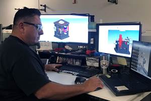
Delcam has released the 2011 version of its PowerMILL CAM system for five-axis and high-speed machining. This release makes the programming of safe toolpaths easier than ever thanks to new stock-model-engagement options that protect both the cutting tool and the machine from excessive loading. Other enhancements include new editing capabilities to simplify the machining of duplicate items; more versatile control of feedrates for leads and links; and extra functionality for sketching, plus the completion of the move to the new clearer forms for the complete range of strategies.
The new release is available now for customers on maintenance to download from http://updates.delcam.com.
The options to optimize tool loading will help overcome a constant conflict for programmers. On the one hand, they want to maximise productivity by setting feedrates as fast as their machines will allow; on the other hand, they need to ensure safe speeds that will not break the tool. The need for safe machining has, of course, become more critical as a growing number of companies are introducing lights-out, unmanned operation overnight or during weekends.
A number of CAM programs incorporate strategies based on the extent of cutter engagement to give more consistent loading on the tool and so allow higher feedrates. However, these options are usually limited to the initial roughing operations, or to only roughing and rest-roughing. PowerMILL’s new stock engagement technology can also be employed with all of the system’s finishing and rest-finishing strategies so ensuring that the safest-possible toolpaths are run on the machine at all stages.
The key to this more comprehensive solution is the accuracy of the stock models produced within PowerMILL after each machining stage has been completed. These models give a precise representation of the material still remaining on the part and are used to ensure that the cutter is never asked to remove more material than it can safely cut. At the same time, the stock models also ensure that toolpaths are not produced where there is no material remaining so the machine tool is never left cutting air.
The new toolpath editing options in PowerMILL will make it easier to produce multiple copies of any duplicated item, for example, when machining a series of cavities into a mold tool. The user can now specify an array of multiple copies in one operation, using approaches such as a number of rows and columns or a radial spacing around a central point. Once the copies have been produced, the complete series of toolpaths can be re-sequenced to minimize tool changes.
Enhancements to feedrate optimization have been introduced to give better control of leads and links at the points of cutter engagement and exit. Typically, the feedrate as the cutter enters and exits the material needs to be slower than that set for the main length of the toolpath. Setting the entry speed too high will risk damage to the cutter and the spindle, and can even move smaller parts on their fixtures. Exit speeds are critical when machining brittle materials, such as graphite electrodes, since the cutter can chip the surface of the part if it is moving too quickly. PowerMILL users can now avoid these problems by setting specific entry and exit feedrates, either as percentages of the feedrate for the main toolpath or as absolute values.
PowerMILL has incorporated sketching functionality for several years, for example to draw boundaries within the model to limit individual machining strategies to particular areas of the part. This has been enhanced with a number of new editing options, including the ability to offset or transform curves, and to flatten 3-D curves into 2-D curves, or to project 2-D curves onto 3-D surfaces.
Related Content
Tolerancing in Mold Design, Part 1: Understanding the Issues of Conventional Bilateral Tolerancing
Mold designers must understand the location, orientation and form limitations of conventional tolerancing before changing to another dimensioning system.
Read MoreWhat is Scientific Maintenance? Part 2
Part two of this three-part series explains specific data that toolrooms must collect, analyze and use to truly advance to a scientific maintenance culture where you can measure real data and drive decisions.
Read MoreHow to Manage Wall Thickness Changes in Your Mold Design
To ensure even filling and cooling, consider wall section transitions, corners and fillets, ribs and bosses, lip and rim designs and CAE flow simulation software.
Read MoreMold Design Review: The Complete Checklist
Gerardo (Jerry) Miranda III, former global tooling manager for Oakley sunglasses, reshares his complete mold design checklist, an essential part of the product time and cost-to-market process.
Read MoreRead Next
Reasons to Use Fiber Lasers for Mold Cleaning
Fiber lasers offer a simplicity, speed, control and portability, minimizing mold cleaning risks.
Read MoreHow to Use Strategic Planning Tools, Data to Manage the Human Side of Business
Q&A with Marion Wells, MMT EAB member and founder of Human Asset Management.
Read MoreHow to Use Continuing Education to Remain Competitive in Moldmaking
Continued training helps moldmakers make tooling decisions and properly use the latest cutting tool to efficiently machine high-quality molds.
Read More


.jpg;maxWidth=300;quality=90)


.jpg;maxWidth=970;quality=90)