
"Rule of Thumb" vs. Engineered Lock Selection
A guide that applies engineering principles is designed to help engineers select properly sized alignment components.
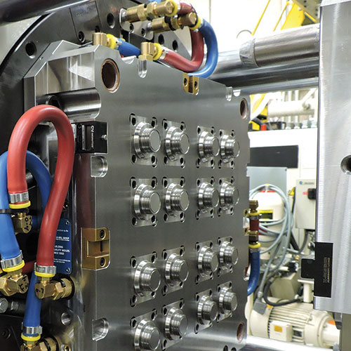
This mold includes properly sized alignment locks that are based on data specific to mold and machine, not just “rule of thumb.” Image courtesy of MGS Mfg. Group.
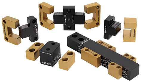
The locks that designers typically consider for use on any given mold are available in a variety of types and styles. Image courtesy of Progressive Components.


Traditionally, designers have relied on a general “feel” or “rule of thumb” to decide which alignment locks to insert within a mold, considering sizes and mounting preference. That’s adequate, right? Maybe not. Selecting an alignment lock based only on gut feel could result in an undersized selection and, down the line, can result in costly mold damage and downtime as well.
The following guidelines for alignment lock selection can help designers make an objective decision. Figure 1 was developed to enable them to match a mold’s size and weight with appropriate alignment lock sizes. By adhering to these guidelines, proper alignment selection and alignment component maintenance should directly result in the elimination of unscheduled mold stoppages due to worn and damaged shut-offs.


Consider what is being lifted. First and foremost, it is important to look at what the moving mold half is being bolted to before looking at the lock and mold base. The moveable platen sizes and weights shown in the table were arrived at in consultation with press manufacturers and after review of molding machine specs. Clearances between the tie bar and bushings were used to calculate how much sag can be expected on a brand new press.
Typically, a mold designer looks at the tie bar location to verify that the mold will fit in the press and that there’s no interference with cylinders or other components, but he or she is not calculating the amount of locking surface required to lift the mounting mold half and engage the platens.
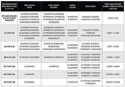
Figure 1 - This guide was developed to help mold designers match a mold’s size and weight with appropriate alignment lock sizes. Figure courtesy of Progressive Components .
For this guideline, maximum weight was calculated using the largest sized mold halves that would mount onto the platens within the tie bars of a particular press. This determined which locks could be tasked with “lifting” the mold halves into place.
Look at engagement. A critical factor that determines what will lift the mold half in the long term is the lock’s thickness, meaning its dimensions from the outside of the mold base in. The maximum load for the engagement ramp of two locks lifting the mold half and platen can be calculated using that measurement and referencing data on leading edge wear for gear teeth (applicable to this situation). (In Figure 1, maximum load was calculated, along with the load-carrying capacities of varying lock thicknesses.) When a mold is closing and being lifted into alignment, it is being cammed into location, essentially acting like gear-tooth engagement.
Rather than radii of mating locks bumping together as the mold closes, gear-tooth profiles were selected for the leading lock edge. This geometry offers more of a lifting effect that glides the alignment locks to engagement. It was proven through real-world testing using a test fixture that duplicated the mold-sag condition. The design goal for a next-generation lock was to see where mold sag occurred in order to arrive at a correlation between lock thickness and mold weight. Initially, a 1/2-inch-thick lock was selected, undersized intentionally for the load to which it was exposed. Leading edge wear occurred consistent with the gear-load recommendation, thereby correlating and validating the test fixture and gear-load information. The load was then increased from 3,000 pounds to 12,000 pounds, far beyond the norm for that size lock, in order to further plot the point of load-carrying capacity from one lock thickness to the next.
Acknowledge that thickness isn’t everything. In Figure 1, industry-standard-sized locks were matched with industry-standard mold bases, with the relative load driving the lock selection. Because data from the gear industry was already being utilized, gear profile geometry was “borrowed” and used as an engagement ramp instead of the traditional use of full-radius-to-full-radius engagement. A variety of materials and treatments were then tested.
Use real-world conditions. Although the harshest testing used to establish these guidelines occurred in an independent lab, it also is important to incorporate real-world conditions to determine such factors as press maintenance intervals, and typical cleaning and re-lubrication recommendations. If a molder is not surpassing 0.01-inch platen sag, and is cleaning and re-lubricating lock surfaces every 100,000 cycles to remove airborne particles that may have accumulated on the surface, then the molder is doing its part in providing the proper conditions for attaining maximum lock life and subsequent mold performance.
Selecting an alignment lock that is appropriately matched for the mold, and following general cleaning and maintenance guidelines, will result in precision guidance. The mold will not be plagued by worn shut-offs, flash and out-of-spec parts; and costly mold stoppage and downtime will not occur.


Related Content

Forces and Calculations Are Key to Sizing Core Pull Hydraulic Cylinders
To select the correct cylinder, consider both set and pull stroke positions and then calculate forces.
Read More
Fundamentals of Designing the Optimal Cooling System
The right mold components can help improve mold cooling and thereby produce higher-quality parts.
Read More
Considerations for Mold Base Material Selection
Choosing the right material can greatly affect the profitability and cost of your application.
Read More
Solving Mold Alignment Problems with the Right Alignment Lock
Correct alignment lock selection can reduce maintenance costs and molding downtime, as well as increase part quality over the mold’s entire life.
Read MoreRead Next

Testing Engineered Options for Mold Alignment
Performance data on alignment components helps select the best treatment, improve the design and chart more precise application recommendations.
Read More
How to Use Strategic Planning Tools, Data to Manage the Human Side of Business
Q&A with Marion Wells, MMT EAB member and founder of Human Asset Management.
Read More
How to Use Continuing Education to Remain Competitive in Moldmaking
Continued training helps moldmakers make tooling decisions and properly use the latest cutting tool to efficiently machine high-quality molds.
Read More