
Rough and Tough
What you don’t know about high-efficiency roughing versus high-speed roughing could be costing you money.
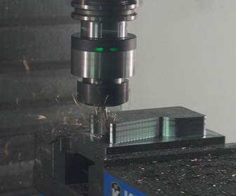
A sensory toolholder and a solid carbide end mill was used to cut 1018 steel on a vertical machining center to prove out some inefficiencies with traditional roughing strategies. Images courtesy of Autodesk.

Figure 1 - Data output proves that a traditional roughing approach yields variation in the cuts.
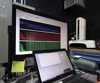
Figure 2 - Data indicate that the tool spends more time at a maximum efficiency cut with adaptive clearing. A traditional roughing approach took 8:09 minutes, while applying an adaptive clearing technique took 2:01 minutes.
Figure 3 - Using a larger depth of cut with a smaller radial cut enables the use of chip thinning calculations to increase the cutter feed rate to maintain chip thickness. A thicker chip pulls more heat away from the tool.
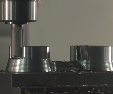
When machining molds with complex 3D shapes, a step-up functionality will give roughed stock a consistent stock allowance.


A common joke that persists in the industry is that you can tell a good machinist from an average machinist by his or her toolbox. However, what is not a joke is that a good machinist can hear the difference between a high-quality and poor-quality cut from across the shop floor. This is especially true when the machinist is performing traditional roughing operations. The associated cutter paths often contain variable chip loads, varying stepovers and, too often, full-diameter-width cuts. Using the right roughing strategy can clear large quantities of material effectively.
Traditional roughing passes are characterized by using a series of offset radial passes. These passes are calculated by offsetting a planar cross-section of the CAD geometry and stock model when necessary, then merging and trimming the two together. With this approach, regardless of the offset stepover value used, the tool will see increased cutter engagement at every internal corner or when driving into slots. These internal corners and slots are where cutter forces spike and when the tool is most prone to breakage. In order to operate at a high feed rate while using traditional roughing strategies, the programmer needs to take a shallow axial depth of cut. This can create other tool issues, as he is now overusing the bottom of the cutter rather than the whole flute length. This causes the tool to store more heat in the bottom versus spreading it out along the whole flute, causing premature wear.


In contrast, a modern high-speed machining strategy for roughing on machines capable of running complex NC files at high speeds, or adaptive clearing, maintains a constant radial tool engagement throughout the entire cut. Constant radial tool engagement eliminates spikes in the cutting forces and allows the programmer to take a larger axial depth of cut, while simultaneously maintaining a high feed rate and extending tool life.
Adaptive Clearing in Action
To prove out these roughing theories, data was logged from a sensory toolholder with a solid carbide end mill cutting 1018 steel on a vertical machining center. A sensory toolholder is a wireless force sensor used for tool monitoring. During machining, it generates force and torque directly at the toolholder. The data can then be transmitted to a receiver and used to optimize machining processes.
First, a traditional roughing approach was used to run the part. Not only could one hear the variation in the cuts, but it could clearly be seen in the logged data. Through graphs, the toolholder sensors show a tale of cutter loads with considerable variation and very sharp spikes, especially in torsion (green) and bending moment (red) (see Figure 1). The spikes indicate that the machine operators need to decrease their feed rates for the worst-case scenario, but the many low areas in the graph mean that for the remaining operations, the program will not be running at optimum material-removal rates.
However, high school pre-calculus tells us that the total area under the graph is what is actually important. The more total area under the graph, the more material being removed and the more efficiently the machining operation is running. The graphs in Figure 1 display several low and flat areas, indicating inefficiency with the occasional spike of higher material removal. Adaptive clearing quickly reaches the maximum efficient machining rate and maintains that rate throughout the cut, then repositions for the next cut. This allows milling at an efficient rate during all cuts with constant cutter forces throughout. Constant forces mean fewer vibrations within the tooling and less shock to the cutting edges caused by those vibrations. This extends tool life and reduces tooling costs.
Figure 2 shows consistency between when the tool is cutting, in all cuts, and when the tool is not cutting. One can quickly see that the tool spends more time at a maximum-efficiency cut, which is indicated by more area under the graph. In real numbers, this means that the traditional roughing pass took 8:09 minutes to complete the roughing operation, while the adaptive clearing technique took only 2:01 minutes.
While saving time is a huge plus, the benefits are deeper than that, including reducing tool wear and breakage, while also having more predictable cutting conditions. For example, a larger axial depth of cut allows the use of more of the cutter flute length without overusing the bottom of the cutter. Additionally, the generated heat is spread out along the whole cutter flute length, rather than concentrated at the bottom of the tool.
Achieving a high metal removal rate (MRR) is the goal, and it is how we reduce cycle time. Higher axial-cut depths require lower radial-cut depths to allow for reliable chip evacuation. By reducing the radial depth of cut, one can increase the tool flute count and increase the metal removal rate. It also enables use of chip thinning calculations to increase the cutter feed rate to maintain chip thickness. A thicker chip will also pull more heat away from the tool (see Figure 3).
Without spikes in material removal rates, setting feed rates for maximum material removal becomes much easier. A shop can use data from the tool supplier or simply start milling and increase feed rates slowly to a level with which operators are comfortable. It is recommended to do this after making the first pass around a block, in case the stock size ends up being a little different than what was programmed.
When machining molds with complex 3D shapes, using a large depth of cut will leave larger “stair steps” in the roughed model. In such situations, machinists should take advantage of step-up functionality so that the roughed stock has a consistent stock allowance. Adaptive clearing uses a strategy of constant cuts with a repositioning move. The inherent benefit is that a climb cutting direction is maintained, whereas in traditional roughing operations there may be periods of conventional milling cuts. Because of this, there may be more retracts than some people are accustomed to when the reposition is over a greater distance. Generally, rapid retracts are fastest. However, stay-down parameters also can be modified. With these parameters, the tool will not retract to the top of the stock but rather stay down as it repositions. In many cases, it is desirable for the tool to lift slightly to avoid dragging the floor during repositioning moves, which could generate undesired heat and premature tool wear.
Increasing metal removal rates, decreasing cycle times and improving cutting consistency is easier with adaptive clearing strategies. These strategies are simple to implement and test, as they do not require special tooling or a special mill, working as well on entry-level mills as on the fastest high-performance mills They also are available for a wide range of CAD systems.


Related Content

Treatment and Disposal of Used Metalworking Fluids
With greater emphasis on fluid longevity and fluid recycling, it is important to remember that water-based metalworking fluids are “consumable” and have a finite life.
Read More
Maintaining a Wire EDM Machine
To achieve the ultimate capability and level of productivity from your wire EDM on a consistent, repeatable and reliable basis, regular maintenance is a required task.
Read More
Solving Mold Alignment Problems with the Right Alignment Lock
Correct alignment lock selection can reduce maintenance costs and molding downtime, as well as increase part quality over the mold’s entire life.
Read More
Forces and Calculations Are Key to Sizing Core Pull Hydraulic Cylinders
To select the correct cylinder, consider both set and pull stroke positions and then calculate forces.
Read MoreRead Next

CAM Standards and Credentials
Autodesk and the National Institute for Metalworking Skills (NIMS) partner to establish the first-ever industry standards to equip students and workers with in-demand CAM skills and credentials.
Read More
Are You a Moldmaker Considering 3D Printing? Consider the 3D Printing Workshop at NPE2024
Presentations will cover 3D printing for mold tooling, material innovation, product development, bridge production and full-scale, high-volume additive manufacturing.
Read More
How to Use Continuing Education to Remain Competitive in Moldmaking
Continued training helps moldmakers make tooling decisions and properly use the latest cutting tool to efficiently machine high-quality molds.
Read More