
Precise Military Parts On Demand
EADS Innovation Works combines 3D imaging/reverse engineering software with additive manufacturing technology to demonstrate a quicker, more cost-effective method for providing replacement parts for military vehicles and equipment in the field.
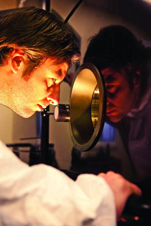
Andy Hawkins, an EADS Innovation Works research engineer, observes an EBM machine.
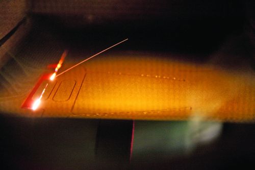
The electron beam scans the titanium powder bed to maintain proper temperature before melting material to make the part.
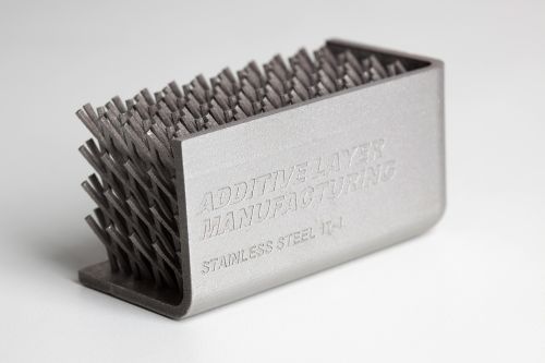
A research organization funded by EADS is the U.K.’s Centre for Additive Layer Manufacturing (CALM), which used additive manufacturing to produce this structure tailored for stiffness.
Geomagic Studio enabled EADS to convert point cloud data into a watertight 3D digital polygon surface model that could be used in the final additive manufacturing process.


Although modern military hardware bustles with advanced technology that seems to verge on the impossible, it often takes several years for the latest technology to be put into regular service. As a result, a proportion of the aircraft and military vehicles that are in use today by armed forces around the world—from tanks to trucks— can be 20 to 30 years old (60 years in the case of the B-52 bomber).
This presents a major challenge when these aircraft and vehicles are deployed to conflict areas, especially if they are located on the other side of the world. When vehicle breakdowns occur, during a conflict or in peacetime, replacement parts must be available where they are needed, without delay.


That means either appropriate spares must be stored where the vehicles are deployed so that they are readily available should they be needed, or they must be flown out as and when required.
The logistical requirement is complex and costly enough on its own. On top of that is the fact that, because of the age of many of the vehicles still in daily use, the procurement or supply of spare parts for these aging vehicles and equipment is becoming more restricted as time goes by. So in many cases, replacement mechanical parts have to be made from scratch—either on demand or for storage for future use. Even with today’s 3D CAD software and CNC machining technologies, this small-lot production adds to the complexity and cost of replacement parts provision.
However, EADS Innovation Works has come up with a possible solution to this growing logistical problem that might result in reduced waste, greater efficiency and faster manufacturing of required parts. It involves the use of a Faro ScanArm 3D laser scanner, Geomagic Studio 3D imaging/reverse engineering software and an Arcam A2 electron beam melting (EBM) additive layer manufacturing system.
Proof-of-Concept Project
EADS Innovation Works is a global network of technical capability centers serving all of the business units of EADS (European Aeronautic Defence and Space Company). These business units include passenger, freight, military and corporate aircraft maker Airbus; military and civil helicopter manufacturer Eurocopter; space transport and satellite systems developer Astrium; and communications and security systems specialist Cassidian.
EADS Innovation Works operates the corporate Research & Technology (R&T) laboratories around the world, and its mission is to identify new value-creating technologies and to develop technological skills and resources that can be of benefit to any or all of the EADS business units.
The project to develop a quicker, more cost-effective way to provide required replacement parts for aircraft and military vehicles is one example of the type of work that Innovation Works takes on. Jon Meyer, research team leader in the Metallic Technologies & Surface Engineering group at EADS Innovation Works’ facility in Filton, UK, near Bristol, outlines the aim of the project as follows:
“This was a proof-of-concept project,” he says. “The whole idea behind it was to demonstrate that additive layer manufacturing technology could cut the time and cost involved in providing replacement parts for aging aircraft and vehicles. Instead of needing to store parts locally or have them flown out, the damaged original part could be scanned, digitally modelled and then produced, on demand, at the same location as the vehicle for which it is required. In practice, each location would be equipped with a 3D scanner, the necessary Geomagic software and a direct manufacturing machine.”
Three-Step Process
Step 1
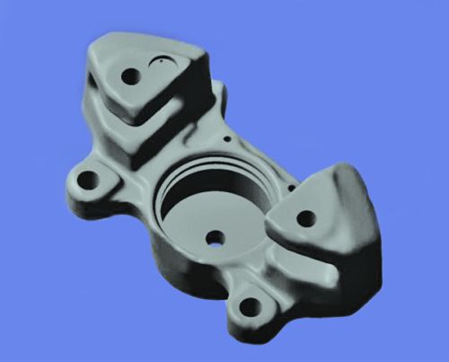
The item the project team selected to use as an example was a brake caliper from a car. The first step was to scan the caliper with the Faro ScanArm laser scanner. This unit can record data at a rate of nearly 20,000 points per second to an accuracy of 0.035 mm. The individual scans required to capture the whole caliper were saved as a series of point cloud files that were then read into Geomagic Studio 3D imaging/reverse engineering software.
Step 2
The team used the tools in Geomagic Studio to convert this “dumb” point cloud data into a watertight 3D digital polygon surface model that accurately reflected the shape of the original caliper and could be used in the final manufacturing process.
The individual scan files were first combined to produce a single point cloud model of the caliper; Geomagic Studio was then used to reduce the point count to a more manageable size (without losing any detail) via the software’s “curve sampling” tools. The data set was also cleaned to remove scanner noise and outlier points that had been picked up during the scanning.
The software then enabled the team to fill in areas that the scanner couldn’t capture fully, such as holes for fixing bolts, which extend from one surface through the caliper to the opposite surface. For holes such as these, the scanner was only able to capture their location and circumference, not their full depth. So the team first created a digital model of the entire caliper without the holes, then used the software tools to clean and sharpen the surface edges of the holes as captured by the scanner. These were then “pushed” through the model from one side to the other to create the bolt holes.
Additionally, Geomagic Studio let the engineers refine and smooth areas of the model using digital sandpaper.
Once the 3D polygon surface model was complete, it was saved as an STL file and exported to the “Magics” additive manufacturing build preparation software from Materialise.
Step 3
After the data had been conditioned in this software, the production of a replica caliper in titanium could begin on the Arcam A2 EBM system.
As with all additive layer manufacturing techniques, the EBM process requires that the 3D digital model of the part that is going to be manufactured first be digitally “sliced” into cross sections—each as thin as 0.1 mm or less. The data representing these cross sections then controls the EBM machine’s movements to form individual layers that are built up, layer by layer, from metal powder melted by an electron beam to create the physical part.
Each layer is melted to the exact geometry defined by the 3D digital model of the part. For each layer of powder, the electron beam first scans the powder bed to maintain the required temperature for the alloy being used. It then melts the contours of the part and, finally, the bulk. Parts are built in a vacuum at high temperature, which results in stress-relieved parts with material properties better than cast and comparable to wrought material.
Realizing the Benefits
While the replica caliper was geometrically accurate in practice, parts produced using this process also need to meet international standards and certification requirements. This is especially so in the case of aircraft parts where meeting internationally agreed certification requirements is essential before parts can be put into use.
In the case of land-going vehicles, however, the process as demonstrated by EADS Innovation Works already has the potential to bring real benefits in terms of providing spare parts in a timely, cost-efficient manner.
The process also brings a number of more general benefits. For example, the additive technology is more efficient than traditional machining—and therefore less costly and more environmentally friendly—in terms of material usage. Unlike machining, additive manufacturing doesn’t start with a billet of material, most of which is then cut away. Irrespective of the part’s complexity, the additive process uses only the amount of material the part requires.
Further, parts can be produced with additive technology on an as-needed basis, where they are needed, resulting in reduced parts-storage and transport costs, as well as reduced delivery delays.
There’s also the benefit that this approach removes one of the steps required in the more traditional process. Specifically, there’s no need for a CAD model. The process is: 3D scan, to 3D digital model, to 3D printed part.
Summary
The process demonstrated by EADS Innovation Works shows clearly that the combination of 3D scanning, reverse engineering software and additive manufacturing technology can cut the time and cost involved in providing replacement mechanical parts for aircraft and military vehicles on deployment—or indeed, for any type of equipment in a situation where parts are needed quickly, but are hard to source.
Neil McLeod writes about the ways in which 3D spatial data capture and modeling technologies help industry, commerce, the arts and academia.


Related Content

Machining Center Spindles: What You Need to Know
Why and how to research spindle technology before purchasing a machining center.
Read More
Treatment and Disposal of Used Metalworking Fluids
With greater emphasis on fluid longevity and fluid recycling, it is important to remember that water-based metalworking fluids are “consumable” and have a finite life.
Read More
Plastic Prototypes Using Silicone Rubber Molds
How-to, step-by-step instructions that take you from making the master pattern to making the mold and casting the plastic parts.
Read More
Moldmakers Deserve a Total Production Solution
Stability, spindle speed and software are essential consideration for your moldmaking machine tool.
Read MoreRead Next

3D Printing for Better Customer Communication
Additive technology helps a mold manufacturer establish better customer communication and create a more productive design process.
Read More
How to Use Continuing Education to Remain Competitive in Moldmaking
Continued training helps moldmakers make tooling decisions and properly use the latest cutting tool to efficiently machine high-quality molds.
Read More
How to Use Strategic Planning Tools, Data to Manage the Human Side of Business
Q&A with Marion Wells, MMT EAB member and founder of Human Asset Management.
Read More