
Part Two of a Two-Part Series EDM’s Effect on Surface Integrity
To improve the potential for success in quality mold production, moldmakers need to understand some specific characteristics of the electrode material as well as certain facets of the EDM process that affect surface finish and integrity.


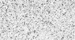
Figures 1a and 1b: Materials of the same classification from different manufacturers. The varying microstructure and porosity can result in significantly different electrical resistivity values. Figures courtesy of POCO Graphite.
Figure 4: Illustration of the energy affect on the altered metal zone depth with tool steel.
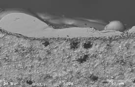
5µ Graphite / Tool Steel 48 amps 50 µS on-time White layer depth 26 - 51 µm
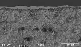
Figure 3: 5µ Graphite / Tool Steel 4 amps 50 µS on-time White layer depth 9.7 µm
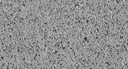
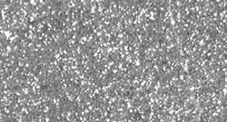
Figure 2: Photomicrograph of copper impregnated graphite.
This is the second of a two-part series discussing the effect that EDM has on the surface integrity of the cavity. The first segment of this article (February 2008) discussed the various layers of the cavity that are thermally affected by the EDM process. In addition, a brief discussion was provided regarding the characteristics of the electrode and workpiece, and how these play an integral part in the EDM process. In this issue, the discussion will focus on specific characteristics of the electrode material and certain facets of the EDM process that affect surface finish and integrity the most. An understanding of these components will significantly improve the potential of success in producing a quality mold.


Electrode Material
There have been many articles written about the various types of electrode material available for EDM. The majority of these articles focus on the microstructure of the material and how this structure—along with the particle size of the material—plays a part in the final EDM surface finish. While the importance of the particle size and microstructure of the electrode material should not be discounted, there is another characteristic that should be considered. This is the Electrical Resistivity (ER) value of the electrode.
The electrical resistivity of a material is the property that determines the resistance to the flow of an electrical current as it passes through the electrode. Materials with lower ER values are better conductors and allow more energy to be applied into the EDM cut. Conversely, materials with higher ER values seem to retain a greater amount of the energy within the electrode and increase the potential of overheating and increasing the overburn.
While graphite is inherently resistant to the current being applied to the electrode, the varying porosity within the microstructure plays a large role in the amount of electrical resistivity of a specific material. The porosity of the material greatly affects the electrical resistivity as these pores are pockets of trapped air and as we know, air has a high insulating value.
For instance, Figure 1 illustrates the photomicrographs of two materials being marketed within the same graphite material classification. The electrical resistivity of the material sample “A” is 871 µOhms/inch while the resistivity value for the material sample “B” is 605 µOhms/inch. As previously explained, the higher ER values cause the material to retain more of the energy in the EDM process, and therefore, could result in larger overburn at the same parameters of the lower ER material.
Using copper as the electrode material significantly reduces the ER value. This is due to the fact that the copper is formed in a molten state and has little to no porosity to account for. In addition to this, copper is one of the best conductors available today so virtually 100 percent of the current applied to the electrode passes through with little being retained. While this may bring a slight advantage to the use of copper as the electrode material, there are other facets of the EDM process that limit the materials performance.
Another electrode material available to the EDMer is a combination of graphite and copper. This is the copper-impregnated graphite whereas molten copper is forced into the porosity of a graphite material. The advantage to this is not only an increase in the strength of the material, but a lower electrical resistivity as the copper in the porosity changes an insulating pore into a conductive one. These materials are very useful when working with exotic metals such as carbide, titanium or copper alloys as the workpiece.
Figure 2 illustrates a photomicrograph of a copper impregnated graphite. The electrical resistivity of this material is 177 µOhms/inch, much less than the ER values of the materials featured in Figure 1. The lower electrical resistivity of the electrode allows for greater amounts of energy to be applied in the EDM cut and reduces the amount retained within the electrode. The advantage of this is often higher metal removal rates with reduced overburn.
Spark Energy
The spark energy is a culmination of three factors: voltage, amperage and on-time. Each of these three factors affects the surface integrity differently and can be adjusted to alter this effect. However, it must be noted that altering any of these factors will not only change the surface finish and integrity, but also could affect the overall EDM performance, in terms of metal removal and electrode wear.
Voltage
Before the current can flow between the electrode and the workpiece, the open-gap voltage increases until it has created an ionization path through the dielectric fluid. Once the current starts to flow, the voltage drops until it stabilizes at the working gap level. The working gap voltage is the distance between the leading edge of the electrode and the workpiece, and is preset by either the EDM operator or the technology within the EDM machine. A high working gap voltage setting will increase the gap and allow for better flushing conditions while stabilizing the cut. A lower working gap voltage setting will squeeze the gap and often results in an increase of metal removal. With this setting, the spark energy is compressed into a reduced distance between the electrode and the workpiece. While this does allow for improved speeds, this compression of the spark also increases the depth of the thermally affected layers and increases the altered metal zone.
Amperage
When discussing amperage, the focus is generally on the average amps applied to the electrode during a complete spark cycle. The reason for this is to prevent overpowering and damaging the electrode. In terms of surface integrity, the amperage considered is the peak current. The peak current is the maximum current applied from the power supply.
For instance, if the program of an EDM cut called for 40 amps in a roughing condition and ran at 50 percent duty cycle, the average amps applied throughout the cycle would be roughly 20 amps. However, when considering peak current, the duty cycle is not a factor and the amperage considered would be 40 amps regardless of the duty cycle. As the amperage increases, the white layer of the cavity becomes thicker and a deeper layer of carbon is present in the cavity. Figure 3 illustrates the variance of two EDM cuts with different amperage.
On-time
The on-time segment of the EDM cycle is the length of time that the peak current is applied to the EDM cut. The on-time is well known as having a direct effect on the surface finish of the cavity as longer on-times result in a rougher cavity finish than shorter on-times. Regardless of the voltage or amperage applied, it is the on-time portion of the EDM cycle that removes material and affects the integrity of the cavity. Amperage and voltage in this case are secondary and affect the EDM process through the on-time.
For the same reason, longer on-times result in rougher surface finishes in the cavity, using an excessively long on-time also will result in a thicker altered metal zone. As the heat from the spark energy transfers into the cavity, the unaffected materials begin to heat, eventually become molten and are ultimately ejected into the EDM gap. As the on-time is increased, it goes without saying that this energy is carried further into the material and changes the properties of the sub-surface layers underneath the EDM cut.
Determining the Altered Metal Zone
Most manufacturers of EDM sinkers today have technologies developed within the generator to calculate and control the depth of the altered metal zone. These technologies should be utilized whenever possible as they are developed specifically for that particular manufacturer.
However, the technologies within the EDM sinker generally allow for a safety factor and will calculate for a small amount of stock to remain within the cavity to ensure the ability to achieve the final desired surface finish. In order to maximize the efficiencies of the EDM cut, EDM operators have been known to calculate the altered metal zone using a formula to determine the amount of energy applied to the cut.
As mentioned earlier, energy is derived by a combination of voltage, amperage and on-time, and is often expressed in units of Joules. The formula for calculating energy is as follows: E = V x A x μS = Joules; whereas E = energy; V = voltage; A = amperage and μS = microseconds of on-time.
If an EDM cut were to have programmed 80 volts with 20 amps and an on-time of 200 microseconds, the calculation would be 80 x 20 x .0002 = .32J. In this scenario, the energy applied to the cavity would be .32 Joules.
By following the chart in Figure 4, it can be determined that this example would result in an altered metal zone depth of approximately 30μ (.0012") if a 5μ electrode material was used. If the electrode material was copper, the altered metal depth would be approximately twice the amount of the graphite electrode at 60μ (.0023").
Why is this? Remember, the copper electrode is essentially a pure conductor and applies more energy in the EDM cut due to a very low electrical resistivity value. As more energy is applied in the cut, the deeper the altered metal zone will be.
Conclusion
Maintaining the integrity of the cavity is essential to producing a quality mold. If the integrity were jeopardized, the life of the mold is significantly reduced—therefore increasing manufacturing costs.
With an understanding of the facets affecting the integrity of the cavity, the EDM’er will be able to optimize the EDM process while mitigating the probability of mold failure due to existing microcracks or flaws within the cavity. As the EDM process is optimized, the potential exists for increased throughput and reduced delivery times.


Related Content

Laser Welding Versus Micro Welding
The latest battle in finely detailed restoration/repair of mold materials.
Read More
How to Eliminate Chatter
Here are techniques commonly used to combat chatter and guidelines to establish a foundation for optimizing the moldmaking process.
Read More
Moldmakers Deserve a Total Production Solution
Stability, spindle speed and software are essential consideration for your moldmaking machine tool.
Read More
Maintaining a Wire EDM Machine
To achieve the ultimate capability and level of productivity from your wire EDM on a consistent, repeatable and reliable basis, regular maintenance is a required task.
Read MoreRead Next

EDM’s Effect on Surface Integrity
Understanding the various layers of a cavity that are thermally altered by the EDM process will help you understand how EDM affects the integrity of the mold surface.
Read More
How to Use Strategic Planning Tools, Data to Manage the Human Side of Business
Q&A with Marion Wells, MMT EAB member and founder of Human Asset Management.
Read More
Reasons to Use Fiber Lasers for Mold Cleaning
Fiber lasers offer a simplicity, speed, control and portability, minimizing mold cleaning risks.
Read More