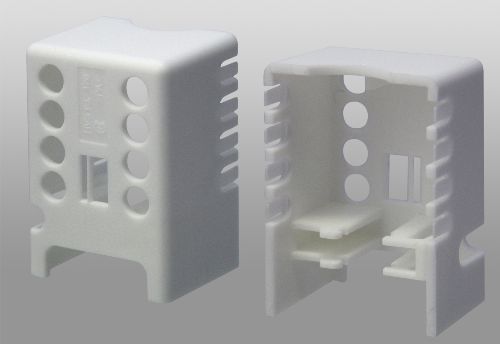
Moldmaker Relies on Plastic Injection Analysis System for Perfect Plastic Cover
When a moldmaker received an order for a plastic cover from a company making electrical coupling components, they began the design and manufacturing process using a plastic injection analysis system, which checks mold design and the optimum placement of injection gates.


When a moldmaker received an order for a plastic cover from a company making electrical coupling components, they began the design and manufacturing process using a plastic injection analysis system, which checks mold design and the optimum placement of injection gates.
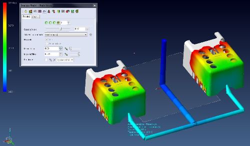
Before TVAR Pardubice (Czech Republic) begins to create technical molds like those ordered by Elektro Bečov for manufacturing plastic terminal covers, they use VISI Flow to optimize the tool design and molding process parameters. This preventative analysis detects a wide range of potential manufacturing issues such as warpage, weld lines, air traps, filling issues and hot spots, while determining the optimum gating position.


Without it, according to Jim Dolezal, Design Office Manager, many problems would not be identified until the molding trial: “If there’s difficulty filling the part it may mean changing the gate, or even moving the gate and runner. This can’t be done on the press, so the mold would have to go back to the toolroom to be reworked, and then back into the mold shop to be sampled again. But VISI Flow detects such problems so we can make the changes before starting to produce the mold which not only helps us to minimise costs but also helps us to save valuable manufacturing time.”
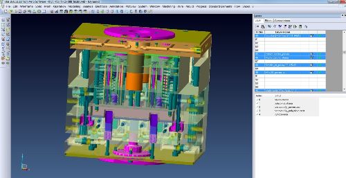
TVAR’s suite of VISI software focuses on all tool and mold issues, enabling them to create complex and high-surface-quality moldings, in four principal industry sectors: technical parts, packaging, consumer goods, and lamination. For example, VISI Analysis analyzes the part through the curvature surfaces analyzer, draft analysis, and different ways of searching split lines and surfaces, along with other analytical tools to diagnose memory elements or compare parts graphically. And VISI Mold provides a complete solution for 3D parametric mold design, based on industry-specific automation to guide them through the entire mold development process.
Bečov Electric’s engineers designed the terminal cover in Solid Edge, and also designed the basic molding; then TVAR used VISI CAD/CAM for the final design, plastic injection analysis and to manufacture the mold. Files were exchanged for comments in STEP format and also verified in Parasolid format. Parts of the molding to be changed were highlighted by color or new alternatives of the molding were suggested. There were several variants of moldings, which were slightly different.
Elektro Bečov delivered product drawings with tolerances and other requirements, and due to the expected high number of products it was agreed to use a double mold with the following spec:
• Dimensions: 296 x 296 x 276
• Slides
• Variable split plane
• Tip, feeding channels, gate and runners
• Ejectors design
• Molding material: PA6
It was at this stage that VISI Flow was used to check the design of the mold and placement of the injection gates, showing a full picture of how the tool would perform in the molding machine, and giving TVAR the confidence to commit to making the mold.
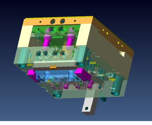
The double mold was designed with the cold tip tunnel gate placed on the front part of the molding, under the lunate sidecut. A cavity plate surrounds the molding from three sides, including cylindrical and shaped protrusions that make up the holes on top and a side wall. There is only one insert, for the label of the cover. The cavity is manufactured by wire erosion machining (EDM).
Due to the open back of the molding and the location of hook-shaped internal partitions, slides containing shaped inserts move to the core plate. Two core plates form a variable split plane – one for each molding.
The shape is manufactured on the milling machine; details are sparked and the forming part is polished.
Due to the need for a good air trap release and planchet endings at the sides of the molding, a venting groove was created along the whole circuit of the molding. Tempering channels run around the shape of the cavity in the cavity plate and in the cavity plate frame. There is a tempered cylindrical cavity with a partition in the center of the core plate. Tempering liquid is supplied there from the frame of the core plate.
The terminal cover is ejected from the molding firstly by the movement of the slides when the mold is opened, and then the subsequent use of ejectors.
Programming for CNC machining is done in the VISI Machining module. Many machining strategies are specially focused on the mold manufacturing, where the main concerns are accuracy, quality and optimization of time and material costs.


Related Content

CT Scanning Helps Micro Molder Reduce Cost of First Article Inspections
CT scanning services performed by 3D ProScan, a division of NyproMold Inc. provides MTD Micro Molding with accurate, high-resolution internal and external measurements performed about seven times faster and at significant cost savings.
Read More
Evaluating Metal Powders for Conformally Cooled Mold Inserts
Mechanical properties and design software techniques reveal the benefits of a modified high thermal conductivity metal powder for 3D printing in moldmaking.
Read More
Surface Finish: Understanding Mold Surface Lingo
The correlation between the units of measure used to define mold surfaces is a commonly raised question. This article will lay these units of measure side by side in a conversion format so that companies can confidently understand with what they are dealing.
Read More
What is Scientific Maintenance? Part 2
Part two of this three-part series explains specific data that toolrooms must collect, analyze and use to truly advance to a scientific maintenance culture where you can measure real data and drive decisions.
Read MoreRead Next

How to Use Continuing Education to Remain Competitive in Moldmaking
Continued training helps moldmakers make tooling decisions and properly use the latest cutting tool to efficiently machine high-quality molds.
Read More
How to Use Strategic Planning Tools, Data to Manage the Human Side of Business
Q&A with Marion Wells, MMT EAB member and founder of Human Asset Management.
Read More
Reasons to Use Fiber Lasers for Mold Cleaning
Fiber lasers offer a simplicity, speed, control and portability, minimizing mold cleaning risks.
Read More