
Mold Design Using Solid Modeling Techniques
Take advantage of solid modeling to simplify the complexity and reduce the time needed to design molds.


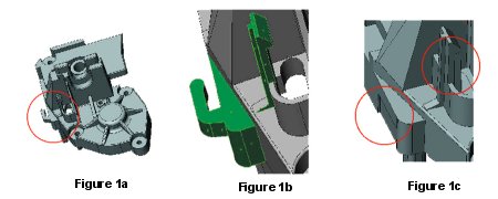
Figure 1a: Original part, 1b: Problem features, 1c: Simplified features.
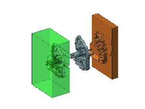
Figure 3: Automatically creating the core object.
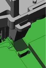
Figure 5: Completed core block.
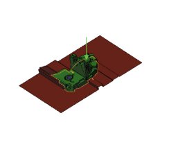
Figure 2: Optimal Parting surface.
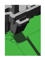
Figure 4: Assembly of the simplified core and original part.
Traditional mold design is accomplished using surface modeling techniques. This approach is still feasible, but can be very time consuming when creating complex molds. With new solid-modeling software, users can create complex parts 10 to 20 times faster than with traditional techniques. This is pri-marily due to the fact that many of the operations are automated:
- Draft angle analysis - Quickly calcu-lates draft and automatically arranges the information.
- Parting line generation - The parting line is automatically generated in such a way that it always forms a closed loop. Problematic segments that are difficult to manufacture can be easily changed with a simple manual operation.
- Parting surface generation - The parting surface is automatically gener-ated using a sophisticated approximation algorithm. The user defines the surface propagation direction and the surface type as either 2.5-D or 3-D.
- Surface assignment - Surfaces are automatically grouped into logical layers such as core, cavity, inserts and sliders. A Drag & Drop feature also is provided for manual assignment.
- Solid core and cavity generation - Splitting a solid block automatically gen-erates the core and cavity objects as solids.
- Associative - Changes made to the model automatically update the core and cavity solids. A tracking mechanism is used to automatically update the information to provide immediate feedback.
This new software system combines the best of solid and surface modeling techniques in one integrated environment. It works on both open and closed (solid) 3-D models and uses standard commands with special extensions. Due to an intuitive user interface, the learning curve is very short - even for novice mold designers.


Solid Vs. Surface Modeling
Having a solid model to create your mold gives you greater flexibility. With a solid model, one can easily make modifications to the part. The example shown in this article is from a benchmark suite for mold design. The geometry is complex and does not offer an easy solution for the parting line and parting surface. Using a surface-based approach would be very time consuming and require manual operations. However, as will be seen in the following example, using a solid modeling approach will drastically reduce the time to create this mold.
Simplify the Design
The original part (see Figure 1a) has an area with zero draft and a hook-like feature (see Figure 1b). Constructing a parting line and parting surface in this area can be quite difficult. This is due to the fact that the parting line is not planar and the part contains features that are not suited for mold design. Upon further inspection, it can be determined that the hook-like feature should belong to the core and the area with the zero draft should belong to the cavity.
With a traditional surface modeling approach, one would spend a considerable amount of time generating the parting line around the hook-like feature. But by using solid modeling software, this feature can easily be removed by introducing a temporary modification to the original part.
Figure 1c shows the simplified model. Simplification of the model reduces model complexity and the amount of time required to generate the parting line and parting surface.
Automatic Parting Line and Surface Generation
Now that the part is simplified, it is possible to generate the parting line and parting surface. The parting line is automatically generated in such a way that it always forms a closed loop. Problematic segments such as undercuts are automatically split and assigned to their respective core or cavity. Holes are filled in and additional changes can easily be introduced using standard commands. The parting surface is automatically generated using a sophisticated approximation algorithm. Notice that the parting surface around the modified area is much simpler and contains material that can be removed later. The result is shown in Figure 2.
It is possible to construct a parting line and surface using a surface-based approach, but this will require hours of manual operations. However, the solid-based approach temporarily simplifies the part to avoid the complex features. This is not possible in a surface-based approach.
Automatic Generation of Core/Cavity Blocks
The parting surface and surfaces be-longing to the original model need to form a "skin." A skin is the set of surfaces containing the parting surfaces, filled holes and the core or cavity surfaces. The skin is used to cut a solid block to create the core and cavity blocks. Features in the new software conveniently organize all of the surface information into folders representing the parting surfaces, core surfaces and cavity surfaces. To complete the core and cavity objects, the user can select an option from the menu and both core and cavity parts are generated as solid blocks. The result is shown in Figure 3.
Putting the Features Back
Now, you need to incorporate the original simplified feature into the simplified core and cavity objects. The hook-like feature belongs to the core. To do this, you create an assembly with the simplified core object and the original part (see Figure 4).
The final step is to perform a Boolean operation, subtracting the original part from the simplified core object. This operation removes the material from the simplified core block where the hook-like feature exists. The result is a core object that matches the exact geometry of the original part (see Figure 5). The same operation is then repeated on the cavity object to recapture the area with zero draft.
Associativity Between Model and Core And Cavity
Another advantage of using a solid modeling approach is the use of associative properties. As the solid model is designed, all operations are tracked from the initial drawing to the final solid. This tracking mechanism allows you to change the part at any stage of the design and automatically update the entire model. For example, Figure 6 contains the original drawing, the solid model and the core/cavity blocks.
Often a design change is needed. In this example, a rib was added to the original part. The original drawing and the core/cavity blocks are updated automatically. Using a surface-based approach, one would have to start the whole process of designing the part and - more importantly - the mold from the very beginning.
Benefits
By simplifying the geometry of the part, it is possible to avoid the complexity and time involved in generating the parting line and parting surface. Using the software's capabilities, the user can easily generate the core and cavity blocks. As a result, this new system provides a powerful, feature-based solid modeler that allows users to make modifications to parts for mold design.


Related Content

The In's and Out's of Ballbar Calibration
This machine tool diagnostic device allows the detection of errors noticeable only while machine tools are in motion.
Read More
How to Manage Wall Thickness Changes in Your Mold Design
To ensure even filling and cooling, consider wall section transitions, corners and fillets, ribs and bosses, lip and rim designs and CAE flow simulation software.
Read More
Mold Design Review: The Complete Checklist
Gerardo (Jerry) Miranda III, former global tooling manager for Oakley sunglasses, reshares his complete mold design checklist, an essential part of the product time and cost-to-market process.
Read More
Mold Innovations Power Unique Auto Lighting Elements on Hummer EVs
Diamond machining, electroforming of micro-optical inserts and modified latch-lock system help injection molds produce unique forward lighting elements.
Read MoreRead Next

How to Use Continuing Education to Remain Competitive in Moldmaking
Continued training helps moldmakers make tooling decisions and properly use the latest cutting tool to efficiently machine high-quality molds.
Read More
How to Use Strategic Planning Tools, Data to Manage the Human Side of Business
Q&A with Marion Wells, MMT EAB member and founder of Human Asset Management.
Read More