Midwest Mold & Engineering - A Case Study in Data Exchange
By changing CAD systems, one moldmaker was able to reduce the leadtime on some projects from days to a matter of minutes.


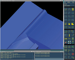
Figure 1: CADKEY: This is a part as imported directly from CADKEY. In the list region, you can see that there are 18 edges that did not stitch together.
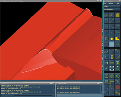
Figure 2: CADfix: This is the same part after running through the CADfix wizard. It may not be visible, but in this part there are numerous surfaces that imported as cylinders complete with centerlines. Also noteworthy is the fact that there are zero edges that did not stitch together.
Mold and die shops come in a wide variety of sizes. Regardless of the number of employees, locations or the customers they serve, these shops play a strategic role in the product development chain. Leading OEMs throughout industry have come to rely on mold and die shops as an extension of their manufacturing operation, providing quality components and services. Needless to say, quality, responsiveness and a demonstrated ability to be flexible is absolutely critical in keeping and attracting customers, and CAD/CAM tools play a key role enabling these shops to function in today's CAD model driven world. While each shop is unique with respect to the type(s) and quantity of software tools they employ, all wage a common battle on a daily basis - fighting the Bad CAD war.
For many, the process of dealing with problem CAD models is slow and painful. Days or even weeks are wasted locating problems and reworking or completely recreating the models before they can be effectively machined or molded. Fortunately, proven solutions now exist.


Located in Pella, Iowa, Midwest Mold & Engineering specializes in the design and building of high volume, precision molds for customers throughout the Midwestern United States. The company employs some of the latest technology using such CAD/CAM software systems as CADkey, SmartCAM, Cimatron and I-DEAS Master Series. CAD model files are received from customers in a variety of formats generally including IGES, STEP and SAT.
Data Exchange Hurdles
In many ways Midwest Mold is a typical mold and die organization. Founded in 1990, the shop faces daily challenges common throughout the industry - to deliver quality parts and service to its customers on time and within budget. The company also is finding that more jobs are being awarded based on a faster leadtime. This means that there is less time to spend on trying to repair or modify files with marginal or bad data. Unlike some other mold and die shops, however, Midwest Mold has found a proven solution to importing problem CAD models.
"Like all mold and die shops, we have experienced our fair share of CAD model import problems," explains Tim Spencer, CNC programmer at Midwest Mold. "One problem with translating data between CAD systems is that not all systems use the same tolerance values when creating data. With one system, a gap of .0002" is acceptable, while the next CAD system thinks you could fly an airplane through it," says Spencer. "Getting CADkey and other CAD system files into SmartCAM and I-DEAS was particularly frustrating and time consuming. Problems in the models generally include missing surfaces, gaps, duplicate points and edges and more," Spencer notes. "In a model file with upwards of 500 surfaces, finding and fixing these problems often took days."
"Another common problem is that when doing healing and stitching operations, the software is moving edges and vertices by a predefined amount in order to fill in gaps," says Spencer. "When we are creating shutoff surfaces, the total allowable mismatch between the A and B sides of a mold is .002 inches. If the healing operation moves a critical edge .01 inch, we create a bad part."
The Solution
Recently the company discovered CADfix - a CAD model repair and translation tool. "CADfix allows us to specify a tolerance value in order to maintain the integrity of our data," says Spencer. "In addition, we also use the software to convert IGES files to STEP and vice versa."
CADfix is now a normal step in the CAD model import process at Midwest Mold. "I take ten to twenty minutes and run incoming models through CADfix as standard procedure," explains Spencer. "The tool checks for duplicate points, surfaces, closed cylinders - which are particularly problematic for I-DEAS - and more. Next I simply verify that the model contains only NURBS surfaces. If needed, I transform all non-NURBS surfaces into NURBS surfaces. The result is generally a model that is 80 percent cleaner and can be used more effectively."
In those cases where more extensive work is needed, Spencer runs the model through a second time (see Figures 1 and 2). This time he locates and highlights problem areas directly on the model. Flagged problem areas are taken back to the designer who can easily make the necessary changes to correct the model. In this way, problem areas in the model are pinpointed for the designer, saving substantial time by eliminating guesswork. "Problem areas are often microscopic and can easily slip through standard checking procedures," says Spencer. "With CADfix we can quickly locate and repair even hidden geometry problems. What once took days has been reduced to a matter of minutes."


Related Content

MoldMaking Technology's Most-Viewed Content 2022: Products
MMT shares the five top-viewed technologies, equipment and services of 2022 in each Engineer, Build, Maintain and Manage tenet based on Google Analytics.
Read More
How to Manage Wall Thickness Changes in Your Mold Design
To ensure even filling and cooling, consider wall section transitions, corners and fillets, ribs and bosses, lip and rim designs and CAE flow simulation software.
Read More
Products and Services for Multiple Moldmaking Needs
New year, new technology roundup! Featured here is a collection of product offerings, from profile milling cutters to industry-specific CAD/CAM software to innovative hot work tool steels.
Read More
Tolerancing in Mold Design, Part 2: Using GD&T to Address Conventional Tolerancing Issues
Mold designers can achieve a single interpretation of workpiece functionality when following the American Society of Mechanical Engineers Geometric Dimensioning and Tolerancing standard.
Read MoreRead Next

How to Use Continuing Education to Remain Competitive in Moldmaking
Continued training helps moldmakers make tooling decisions and properly use the latest cutting tool to efficiently machine high-quality molds.
Read More
Are You a Moldmaker Considering 3D Printing? Consider the 3D Printing Workshop at NPE2024
Presentations will cover 3D printing for mold tooling, material innovation, product development, bridge production and full-scale, high-volume additive manufacturing.
Read More
Reasons to Use Fiber Lasers for Mold Cleaning
Fiber lasers offer a simplicity, speed, control and portability, minimizing mold cleaning risks.
Read More