
Micro-Milling Opportunities and Challenges
An integrated approach to the design and machining of micro-milling components is key for mold manufacturers looking to capitalize on this growing opportunity.


We are all familiar with the phrase “the world is getting smaller.” However, it is not just that the world is getting smaller; practically everything we use is getting smaller.
Not only are things getting smaller, they are packed with more components to provide added power and functionality. Micro-size components have a wide variety of applications in almost every industry, including aerospace, automotive, electronics, healthcare, information technology and telecommunication.
The increasing demand for micro-scale components and products presents moldmakers with new and diverse challenges—ranging from the use of new materials to special mold coatings, milling parts with 0.1mm diameter tools and achieving sub-micron-level accuracy.
At the same time, it is the inherent complexity of micro-components that brings about new opportunities for moldmakers. At a time when production of simple and medium complexity molds is shifting to countries with low labor cost, U.S. and European moldmakers can turn to more advanced technologies such as micro-molds and micro-milling to maintain their competitive edge.
An integrated approach to the design and machining of micro-milling components is key for moldmakers that are looking to capitalize on this growing opportunity.
Micro-Milling Machine Requirements
With multiple elements working in tandem, a machine is only as good as its weakest individual component. Less forgiving than traditional milling, micro-milling requires each machine component to be suitable for the unique requirements of the task.
Machine Geometry
Machine geometry determines the machine’s stiffness, accuracy, thermal stability, damping properties, throughput and ease-of-use. The most popular vertical machine geometry types are bridge and C-frame construction. With the spindle or Z-axis being the only moving axis, a C-frame construction offers the best stiffness qualities. Since stiffness directly affects accuracy, this design is highly suitable for micro-milling.
Machine Construction
One of the challenges when milling delicate and accurate parts is minimizing vibrations. Machine tools with greater damping will absorb more of the vibrations induced by cutting. The most suitable machine frame material for micro-milling is polymer concrete, which provides up to 10 times higher absorption of vibrations than cast iron. Polymer concrete also provides superior dynamic and static rigidity and has substantially better thermal stability than cast iron, all crucial properties for small part accuracy.
Guide Way System
The machine tool way system includes the load bearing components that support and guide the movement of the spindle and table. The two most common guide way types are boxways (sometimes called hydrodynamic ways) and linear guides. The boxways used in a large percentage of machines today are problematic in applications that require frequent axes reversal and low friction motion for extreme accuracy. Linear guide ways that offer low static and dynamic friction are the better choice for a micro-milling machine.
Drive and Motion Technology
How small of a part you can successfully machine depends greatly on the drive and motion technologies built into the machine. A ball screw driven by servo motor is the axis drive mechanism used in most machine tools, and is also the most suitable for micro-milling machines. Most important, though, is how the drive and servo motor work together to provide precise and accurate motion in order to produce miniature size 3-D features.
To ensure the most precise axis position, micro-milling applications require glass scales to be placed close to the guide ways in order to provide additional feedback to the control. Micro-milling applications will most likely necessitate the use of 0.1 micron glass scales rather than the commonly used 0.5 micron version.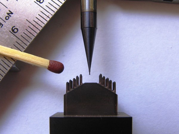
The increasing demand for micro-scale components and products presents moldmakers with new and diverse challenges.


Spindle
The ideal spindle for micro-milling is a closed-loop or vector-controlled spindle, which supports a wide range of speeds and offers full torque at low speeds, rigid tapping capabilities and consistent spindle orientation. A well-designed vector-controlled spindle on a micro-milling machine will offer great flexibility along with the ability to cut even the most difficult material. A 50K-rpm spindle would be quite adequate for most micro-milling applications, which use smaller size tools.
Toolholder and Spindle Interface
HSK toolholders offer a number of advantages for high rpm spindles and thus are the preferred choice for micro-milling machines. HSK toolholders are retained in the spindle by a set of internal grippers located inside the spindle. As rpms increase, metal-to-metal contact between the toolholder and the spindle is maintained because centrifugal forces cause the internal grippers to expand within the toolholder, pressing it firmly against the inside of the spindle shaft.
HSK tooling is also a dual contact interface. It locates on both a shallow taper and a flange creating a precision fit. This precision fit allows the interface to have superior run-out conditions compared to steep tapered tooling. When working with very small cutters, run-out inaccuracies can cause premature cutter failure. Excessive run-out can also reduce the life expectancy of the spindle. Therefore, run-out inaccuracies for micro-milling machines should be kept at 1 micron or less.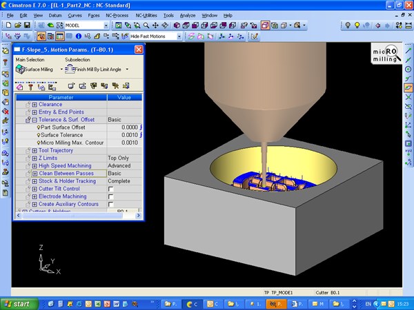
Micro-milling software and NC application for milling micro-components.
CNC Technology
While adequately covering the topic of CNC technology is beyond the scope of this article, two important aspects need to be pointed out:
1. Control interface: the interface should be logically laid out and simple to use, yet flexible enough to handle even the most complex toolpath output from any CAD/CAM system.
2. Processing speed: motion control and feedback are crucial for precision micro-milling applications. The control must be able to quickly process high-density complex data and command the motion to the axis in a precise manner.
Auxiliary Components
Tools that can hardly be seen by the human eye are nearly impossible to measure mechanically. Using a laser measuring system, both the length and diameter of tools as small as 40 microns can be reliably and automatically measured.
Setting up a micro-milling machine can be made easier with the use of a touch probe. Automatic centering, part zeroing and part alignment can be used to quickly establish part orientation. Additionally, part measuring can be accomplished using many of the touch probe routines commonly found on controls that feature probing.
Machine Environment
The machine environment must have a controlled temperature and free from vibrations. If the machine is not properly isolated, even a heavy truck that passes outside the facility could generate enough vibrations to leave its marks on the surface.
Micro-Milling CAD/CAM Requirements
In order to guarantee the level of accuracy, smoothness and continuity that is necessary in the micro-milling environment, the CAD/CAM system must be carefully tuned and optimized to support the following requirements.
Data Translation
A translation error resulting in a 0.005mm gap between two surfaces might not be problematic in a large part, because the part can be polished. However, polishing is typically not an option in miniature molds or micro components, so a gap of the same size in a micro-milled part would be clearly visible. Therefore, the CAD/CAM software should be capable of reading native format files from other CAD systems to keep the integrity of the geometry. Data translation issues between separate CAD and CAM packages can also adversely affect machining accuracy. An integrated CAD/CAM package minimizes the risk of introducing such inaccuracies.
Tight Tolerances
Working with tight geometric tolerances when generating parting surfaces and creating geometry for slides, lifters and ejectors is essential in order to prevent gaps between surfaces, and keep C1 and C2 continuity. The software should support toolpath calculation with tolerances down to 0.01 micron while considering the constraints of the machine used. Such tight tolerances require special toolpath algorithms with greater accuracy and better point distribution in order to achieve a polish-free surface. 
More and more industries (medical, optics, computer components, etc.) depend on the ability to cost-effectively manufacture very small, high-precision molds and parts.
Machining Strategies
The software should support machining strategies optimized for micro-milling, such as maintaining a constant chip load for the rough and re-rough procedures. The ability of the software to support efficient roughing strategies with constant chip load and varying feedrates is critical for micro-milling. To generate a smooth toolpath, the software should support the use of multiple cutters with different spindle speeds, feedrates and cutting parameters in a single finishing operation.
Tool Motion
Rounding can become a challenge in micro-milling, which commonly features very small stepovers. Rounding smaller than the stepover will likely create a sharp motion, while round corners larger than the stepover could create ridges and gaps between sequential passes and generate excessive scallops.
To prevent such gaps and ridges and ensure high surface quality, support for tool motion techniques such as CBP (Clean Between Passes), CBL (Clean Between Layers) and Ridge Machining is a key requirement for micro-milling success.
Multi Axis
A growing number of micro-milling applications require multi-axis machining, such as the use of 5-axis machining for miniature impellers. Five-axis machines enable the utilization of small tools with tilt options that result in better surface quality while eliminating the need for multiple tools. Compared to conventional 5-axis applications, micro-milling applications require greater flexibility in controlling the tool orientation, as well as the ability to track the stock model across multiple dimensions.
Knowledge of Remaining Stock
Knowledge of actual remaining stock throughout the entire process allows the software to adjust the feedrate to actual tool load, in order to shorten machining time while protecting the delicate tools from breaking. As the workpiece shape dramatically changes during the roughing operation, the software simulates the remaining stock after each layer. This enables the tool to go into locations that were cleaned by previous layers, allowing shorter tools to cut into deep areas.
To reduce tool load during the finishing passes, the software should be able to address re-rough operations within the re-machining procedure, while using the remaining stock knowledge.
Geometry Mending
Almost every CAM programming job requires some geometry mending procedures. In many cases, only during the programming process does it become clear that a certain geometry modification is required. Surfaces must be extended to protect the areas that will be machined in another setup, and a draft angle should be applied. CAM software that includes built-in CAD capabilities and provides the assisting geometry with the appropriate accuracy and tangency enables this design-for-tooling mending to be performed by a toolmaker who understands the machining process, such as the NC programmer.
Summary
Micro-systems and micro-milling bring about new opportunities for moldmakers who are seeking to differentiate themselves, generate business in an emerging and lucrative market segment, and be better positioned against lower-wage competitors. New materials, new machining capabilities and innovative CAD/CAM software are available now to help moldmakers step up to the challenges and capitalize on the growing demand for micro-milling.
Contributors:
Hari Sridharan is the Vice President of Engineering & Business Development for Cimatron Technologies, a leading provider of integrated CAD/CAM solutions for mold, tool and die makers as well as manufacturers of discrete parts. With more than 20 years of experience in the industry, Hari began his career supervising a CNC milling department at Isro Satellite Centre in Bangalore, India. He was quickly promoted to Senior Supervisor and later acted as Senior Engineer and Scientist, while managing a tool room with 30 employees. Hari joined Tool Matic of Malaysia in ’94, and branched out into CAD/CAM. While in Malaysia, Hari also worked for Saeilo Japan as a CAD/CAM Application Engineer using Cimatron software. Impressed with the Cimatron software, Hari joined the Cimatron team in 1999 and has been leading the Cimatron engineering team ever since. Hari has contributed greatly to the company’s success through his leadership, dedication and expert skill set.
Gary Zurek is president of KERN Precision, Inc., a subsidiary of KERN Micro- und Feinwerktechnik GmbH & Co of Germany, a world leading supplier of micro, ultra and nano precision machining center. Prior to joining KERN, he held the position as the national applications engineering manager for another major machine tool builder. He has more than two decades of experience in manufacturing and holds a Bachelor of Science degree in manufacturing engineering from Connecticut State University.
For More Information:
Cimatron
(248) 596-9700
info@cimatrontech.com
lsterling@cimatrontech.com
cimatrontech.com
KERN Precision, Inc.
(508) 943-7202
info@kernprecision.com
kernprecision.com


Related Content

How to Improve Your Current Efficiency Rate
An alternative approach to taking on more EDM-intensive work when technology and personnel investment is not an option.
Read More
Mold Builder Uses Metal 3D Printing to Bridge Medical Product Development to Production
Westminster Tool uses metal additive manufacturing for medical device OEM, taking lessons learned from R&D in the prototype mold phase to full-scale production molding in a fraction of the time.
Read More
Mold Builder Uses Counter-Intuitive Approach for Mold Challenges
Matrix Tool Inc. answers customers’ hard questions with creative solutions for cavity spacing, tool sizing, runner layout and melt delivery that reveal the benefits of running in a smaller press size at lower cavitation but higher yield.
Read More
Pennsylvania Mold Builder Doubles Footprint, Maintains Quality and Company Values
Quality Mold Inc. doubles its manufacturing footprint but maintains its private company values and structure, delivering quality and fast turnaround from mold design and build through sampling.
Read MoreRead Next

How to Use Strategic Planning Tools, Data to Manage the Human Side of Business
Q&A with Marion Wells, MMT EAB member and founder of Human Asset Management.
Read More
Are You a Moldmaker Considering 3D Printing? Consider the 3D Printing Workshop at NPE2024
Presentations will cover 3D printing for mold tooling, material innovation, product development, bridge production and full-scale, high-volume additive manufacturing.
Read More
Reasons to Use Fiber Lasers for Mold Cleaning
Fiber lasers offer a simplicity, speed, control and portability, minimizing mold cleaning risks.
Read More