Machining Molds with Negative Stock Shutoffs
Negative stock shutoff can help you make better molds in less time. Here is a clear definition and description of the process. While the concept is fairly simple, the implementation can be challenging.
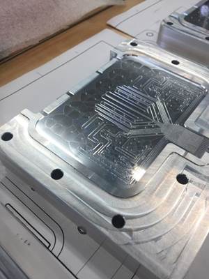
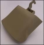
Imagine seeing the finished core for a plastic injection mold, and the blank block for its mating cavity, 40" x 12" x 6", still un-machined on the floor next to it. Imagine being told that the completed mold would be in trial the following afternoon. “Impossible!” would be a natural reaction, yet imagine witnessing the mold trial and acceptance of that completed mold the very next afternoon. The mold was for part of a Toyota automobile grille about three feet long and four inches wide. The cavity was machined automatically and unattended through the night, and the completed mold was in fact accepted at the first trial the next afternoon.
This application teaches that the old tedious art of mold building can be transformed into scientific mold manufacturing through the deliberate integration of programming, machinery and tooling (see Figure 1).
Negative Stock Shutoffs Defined
Historically shutoff areas were carefully and tediously spotted and custom fit, so that the cavity and core sides would actually hit one another and shut off the plastic in the mold—restricting the plastic’s flow to the cavity and runner areas. Spotting the mold is an art form, requiring skill and patience. The result is a custom-made parting, each mold unique because of its fitting.
The name “negative stock shutoffs” refers to the concept of leaving a negative stock allowance; indeed a gap for the mold’s parting line and shutoff! The manufacturing technique can provide shorter leadtimes and higher profits. The mold’s benefits are longer life and better performance.
The gap is small, not big enough to allow any flow of the plastic, so the mold still shuts off. About 0.0008" is normally a good allowance for most plastics, though that gap varies depending upon the material being molded. For best results, the negative stock allowance must be taken from the show face, normally the cavity, so that the larger area around the parting slightly overlaps the hidden, inside face of the part.
Many Benefits
Eliminating the spotting process is a big win for all parties. Historically, fitting and spotting is one of the biggest and most costly labor components in the moldmaking process. It also is unpredictable, often delaying the mold’s completion, tryout and/or acceptance. Eliminating the spotting can shorten leadtimes and reduce the cost. Perhaps even more important can be the benefit of transforming moldmaking from art to science. Keeping the mathematical shape of the mold contours intact means that molds can be repaired more easily, and inserts can interchange.
The lack of interference and impact when closing the mold extends the tool’s life. The mold’s gap is maintained by four contact pads built into the corners of the mold, as well as the sprue and runner area. Since the precision surfaces of the mold aren’t striking cavity to core, those surfaces aren’t prone to the wear and deterioration historically suffered. By eliminating the impact, softer mold steels may yield equal or even superior results, while also providing you, the mold manufacturer with a faster mold manufacturing process.
The gap also makes the mold work better. The need for venting is resolved automatically by negative stock shutoffs, since the air is never trapped. Less force is required in the press to hold the mold shut and to inject the plastic. Faster cycle times with lower forces improve the mold’s results.
The impressive combination of benefits makes negative stock shutoffs enticing; faster and cheaper molds, longer mold life, faster cycle times in smaller presses. How can we implement negative stock shutoffs today?
Starting the Evolution
In a general sense, negative stock shutoffs are most successfully taken on as an evolutionary process. Start today by forcing the tolerances out of your work. Hold the entire mold building process to a tighter tolerance. As we reach a state of proven performance, the confidence and the results will follow. A transformation occurs from the art of mold building to the science of mold manufacturing.
A sweeping implementation of today’s technology makes negative stock shutoffs practical. High-performance CAM systems make tighter, more accurate toolpaths in less time. Reliability in the cutter path area is essential to confident unattended machining through the nights and weekends. High-performance CNC machines automate the machining while cutting faster and more accurately. Slick fixturing, holders and cutting tools combine with it all to deliver better looking molds in record time with implicit accuracy.
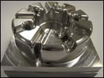
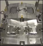
To demonstrate the concepts of negative stock shutoffs let’s examine a steeply contoured male and female set with two-degree draft and 0.0008" clearance all around (see Figure 2). Four corner pads limit the part engagement to 0.0008", yet there is no detectable sideways movement or rotation.
To better understand the critical tolerances required for negative stock shutoffs, consider the tolerance relative to steep cavity and shutoff walls. On a two-degree draft angle, 0.0005" difference in Z depth is less than 0.000020" in the X/Y plane. Working to such close tolerances requires close attention to all the details with the best tools available.
All of these aspects—the programming, tooling and machine—work together for the success of negative stock shutoffs. The accuracy of the end product relies on accuracy each step of the way. Efficient program execution demands better machine and tooling performance. Tool life demands better programming and machine performance. Efficient machine operation demands tight, accurate programs to guide the motion and tools that are durable and accurate. The three components are inescapably intertwined, each relying on the others for its own success.
Surface Model
Did you know that most of the popular CAM systems are not really working with the mathematical NURBS (non-uniform rational b-splined) surfaces that define your part? In fact, one of the first steps most systems perform is to create a tiled or “tessellated” surface that helps them work faster. Unfortunately, this creates a compromise in accuracy. What we gain in speed sacrifices quality. This flaw can be minimized by tightening up the surface tolerance when creating the native file within the CAM system, but again this slows the system down. The best approach still seems to be to work from the actual part surface model, eliminating the intermediate part model step.
Tighter Data
“Garbage in, garbage out” is a familiar expression regarding computer programs. The opposite is true too. Negative stock shutoffs rely on tight and accurate cutter paths to make accurate parts. One key can be choosing a cutter path tolerance that will keep your part well within tolerance and give the CNC machine the information it needs to run optimally.
The latest high-speed CNC machines run best with more data. This means that you can specify tolerances of 0.0001” to 0.000050" for your CAM output. Not only should this be okay for your CNC, but in general, it will run better. The smaller directional changes in each move are actually easier for the CNC to execute accurately than fewer moves with sharper deviations.
This requires more cutter path, with more small moves. Today’s fast computer processing power and direct networking of your CNC with the CAM system enable efficient operation with larger cutter paths [see Beyond DNC at http://www.mmsonline.com/articles/019605.html].
Machine Design
Today’s high-performance CNC machines can move faster and more accurately than in the past. This is the result of both machine design and controls. Faster electronics, more responsive drive systems, and more dynamic mechanical designs work together for speed and precision (see Figure 3).
Traditional box ways are increasingly being replaced because of the large surface areas and the resulting friction. Linear guideways’ ball bearings are highly responsive with minimal friction, but they suffer a lack of damping because of the balls’ pinpoint contact areas.
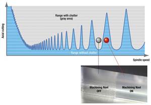
Chatter and vibration are a common issue. Increasingly, the way design of choice is linear roller ways. The linear contact surface of the roller on its way surface helps transfer forces through the machine components to the foundation, stemming vibration. The end result is a more responsive machine without sacrificing finish quality.
Improved dynamics from the machine don’t just get the part finished faster. They make the tools last longer too. Cutters are designed to be shearing the material, not rubbing it away. If we can maintain the designed chip load for any particular cutter, the cutter’s life will be prolonged. Whenever the chip load is less, the effective rubbing action wears away at the cutting edge. Thus, the better the machine can accurately accelerate and decelerate, the longer the cutter life will be. A side benefit will be a more uniform finish for a better looking part.
Look Ahead
The time required for acceleration may vary, but in all cases that time demands a key component for the controls, look ahead. This is a big topic, worthy of an article all on its own merit [see A Closer Look at Look Ahead at http://www.mmsonline.com/articles/039603.html]. In a nutshell though, cutter paths for complex contours will generally suffer violations without look ahead.
The most common and obvious flaw with CNC program execution is rounded corners where the machine basically takes a shortcut rather than executing a sharp corner as at point H in Figure 4.
The more insidious flaw is overshooting when points get bunched together. Historically, NC and CNC machines executed a single move at a time. Because of the slower feedrates and lesser ability to generate cutter paths, each successive block move generally allowed sufficient time for its own acceleration from a stop up to speed and deceleration back to a stop. As CAM and CNC has progressed, the data density and feedrates have increased to a point where the motion flows through the points, an essential capability for today’s mold manufacture.
The catch is that if we blindly flow through the points assuming that we can stop on a dime, we are bound to be stung by overshoots. If we feed through this contour at five inches per minute, we won’t likely encounter a problem. If, on the other hand, we flow through these points at 300 ipm, most machines need to start slowing down by point C to accurately make the corner at point F. Otherwise, the machine will overshoot through point F, violating the part and jerking the machine.
Limited performance in the machine’s look ahead or lack of it altogether not only causes part violations, but also can result in excessive stress on cutters or even tool breakage. Further, the resulting machine jerk causes excessive wear on the machine drive components and ways.
Spindles
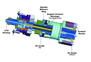
A machine that can move fast also needs a fast spindle. Old fashioned belt or gear-driven spindles simply won’t do in that case, so cartridge-type spindles, integrating the motor and windings as an integral part of the spindle assembly itself should be used. This eliminates the additional heat and vibration of the drive system. To keep the spindle’s temperature under control, add cooling—circulating liquid through chambers surrounding the motor windings and bearings. Refrigerated chillers keep the liquid at a constant temperature to keep the spindle and machine head from growing.
HSK Tooling
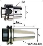
Higher spindle speeds require more accurate, balanced tooling. Secure retention of the holders is especially important at high speeds. The 7/24 taper developed over half a century ago and sold today as CAT, BT and ISO wasn’t intended for high spindle speeds. The prevailing technology today is HSK, developed as a standards defined by a DIN (German Institute for Standards) committee about 10 years ago. HSK tooling comes in several styles, but overall enjoys high stiffness with very low runout because of the designs (see Figure 5). Alignment is from both the taper and the face. Balancing is critical to high rpm, so many of the HSK designs are completely symmetrical to avoid common areas of imbalance like drive keys. HSK tool retention is intended for security throughout the designed speed range, and is actually intended to get tighter with increased speed [see HSK Characteristics and Capabilities at http://www.mmsonline.com/articles/100105.html].
Shrink Tooling
One of the tooling developments that HSK holders helped proliferate is shrink fit. This simple application of physics uses the fact that heat expands and cold shrinks to hold the end mills in the holders. By eliminating the common setscrew of the Weldon style holder, and the collet used so widely in other holders, runout and imbalance are substantially eliminated. Shrink tooling commonly runs true within less than 0.0001".
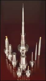
Shrink tooling benefits the user in several ways (see Figure 6). First, the tools run more accurately, so your parts will be more accurate, a pivotal requirement for the purposes of this article where our job’s success or failure hinges on a match of just 0.0008" from the cavity to the core. The milled surfaces look better too. An additional benefit of the accuracy is that the end mills cut on all flutes. This means smoother performance, better finish, and better tool life.
Shrink tooling allows additional benefits. Holders don’t need a collet or setscrew to hold the cutter so they can be made in very slim profiles to provide access to unusually tight places, allowing shorter, less costly carbide for more challenging applications. Even if you own five axis or 3+2 axis machines, slim shrink tooling can help you reduce five-axis setups, eliminating the essential interference checks and increased program complication.
Cutting Tool Accuracy
The accuracy of the actual cutting tool itself is another key ingredient to success with negative stock shutoffs. Working to such close tolerances, we can’t accept deviations from true shape in our cutting tools (see Figure 7).
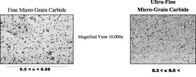
Some of the innovators in the tool industry offer ball end mills individually certified to within three microns accuracy, true four-flute ball mills with center cutting performance on all four flutes.
As with shrink holders, accurate cutter shape again gives a win-win; the accuracy makes a more accurate part, and also ensures higher productivity and longer tool life by providing a more uniform chip load per tooth.
Cutter Geometry
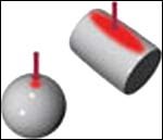
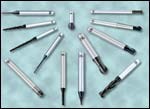
A wide variety of cutter shapes can make a big difference in your machining efficiency (see Figure 8). To that end, consider metric tooling. Your CAM system doesn’t care if your tooling is inch or metric. In general, the rest of the world outside the U.S. works in metric, so there is a bigger market and thus, more choices. This means you can tailor the cutters to the job at hand.
The simple choice here is the length-to-diameter ratio. While we may find two or three choices for standard, long and extra long cutters, metrics often offer many more choices. A great example of this is cutters profiled for rib milling. Available in many ball diameters and draft angles, most sizes come in 2-mm length increments, from stubby to the longest practical lengths.
When the need is more complex, various other shapes can fill the bill with a combination of long reach and stiffness. The key can be the availability of stock cutters to eliminate the need for cutter modifications.
Accumulation of Tolerances
As we have seen, for successful negative stock shutoffs, we need to strive for perfection right from the beginning, working with an accurate 3-D model of the part surfaces, through cutter path creation and execution, using the best techniques and tooling combined throughout (see Figure 9).
Interestingly, the story comes full circle as any mold is completed. Documentation of your process is pivotal to your implementation of it. Recommended is a wall of notebooks with each one dedicated to a job, in which that job is tracked right down to the cutter speeds, feeds and even the feed overrides used. By tracking cutter performance, life and tool deflection, the process can be optimized continually.
A clear channel of communications between the shop and the programmers is a must. Virtually all CAM systems have a tool database, but too often it isn’t used. If the actual machining data is used to update the tool database, all programmers can create an optimized toolpath that runs efficiently and consistently.
Using Negative As Your Positive
Formerly impossible demands for high quality and short delivery can now be satisfied with negative stock shutoffs. Combining the latest technology in programming, tooling and machine tools yields big benefits. You can actually go beyond zero tolerances in your molds to intentionally leaving a slight gap at the shutoff. You can deliver in less time and your mold works better because of the integral venting. Eliminating the surface-to-surface contact reduces the molding press tonnage and improves your mold life. The more you do it and document your process, the better you get—further improving your results and building your own company’s competitive advantage. “Win-win” seems like a real understatement. Building your molds with negative stock shutoffs can be a real positive for you and for your customers.
The AMBA Traveling Seminar
The American Mold Builders Association’s (AMBA) new educational series of traveling seminars focuses on how the latest high-speed programming, tooling and machining techniques combine to change mold manufacturing. The program was jointly developed by Doug Noxell with OSG Tap & Die’s West area manager, Roger Goble and Creative Evolution vice president Todd Schuett.
When Mold Craft Inc.’s Pete Manship became president of the AMBA, he proposed the establishment of traveling seminars to provide information for all chapters on both the business and technical sides of the mold business.
To date, nearly 200 attendees in Chicago, Grand Rapids and Minneapolis have learned about various aspects of high technology mold manufacture through these innovative sessions.
The topics are varied and complex. Machines and controls, programming software and techniques, cutting tools, holders and fixturing are all covered in depth in four hours. Many examples are used, not only in discussion with clear and colorful illustrations, but also with actual videos of parts as they are being produced. Specific techniques are covered in detail and provide a catalyst for audience interaction.
One of the unique aspects to this presentation is the format. Three instructors interact throughout the program to keep it interesting and lively, while presenting the topics from three different perspectives.
Related Content
Moldmakers Deserve a Total Production Solution
Stability, spindle speed and software are essential consideration for your moldmaking machine tool.
Read MoreHow to Eliminate Chatter
Here are techniques commonly used to combat chatter and guidelines to establish a foundation for optimizing the moldmaking process.
Read MoreControl Helps Push the Limits of Five-Axis Micro Mold Machining Accuracy
Toolmaker quickly meets the demands of critical medical device manufacturers with a new five-axis machine tool equipped with the right control technology.
Read MoreMachining Center Spindles: What You Need to Know
Why and how to research spindle technology before purchasing a machining center.
Read MoreRead Next
Advanced Cutting Tools Translate To Greater Cost Savings
Increasing initial tooling investments will allow moldmakers take home more profits at the end of the day.
Read MoreAre You a Moldmaker Considering 3D Printing? Consider the 3D Printing Workshop at NPE2024
Presentations will cover 3D printing for mold tooling, material innovation, product development, bridge production and full-scale, high-volume additive manufacturing.
Read More









_300x250 1.png;maxWidth=300;quality=90)


.jpg;maxWidth=300;quality=90)


