
Lessons in the Use of Electroformed Nickel Tools
Solutions to problems moldmakers face with today’s styling requirements in the instrument panel tooling industry.


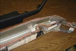
Armrest rotocast tool with 360-degree handle and finished part from another tool with a slightly different shape.
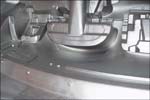
Class A surface close-up of driver side tool showing depression and recesses. Photos courtesy of FET Engineering.
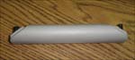
Small hand grip for a door panel made with a rotocast nickel tool.
|
Machined and etched steel injection molds are the dominant tooling used for low- and mid-priced automotive interior and exterior parts; however, in mainly high-end vehicle manufacture, electroformed nickel is selected to produce tools for soft touch interiors because it can be used to duplicate fine grain details in lightweight tools for slush molding. Deep recesses and undercuts can be produced to allow installation of trim, AC vents, radios, head-up display projectors and concealed air bag deployment doors. PVC has excellent release from the nickel. The newer urethanes are more difficult to release from nickel and cost five times more, but are being used to develop a green content when the car is scrapped.
Electroformed Nickel ToolingThis process essentially involves growing a nickel surface on top of a fiberglass and epoxy plating mandrel in an electroplating bath. The mandrel is developed from an automaker’s approved design from CAD files. For nickel tools of various applications, the plating might be 0.080" to 0.250" thick and free standing or mounted in a steel frame with a filled epoxy mass casting for load bearing. An average nickel shell for an instrument panel slush mold tool would weigh about 150 pounds. A completed RTM tool for a Class A truck roof might have two matched nickel shells weighing 1,000 pounds each, but the composite mold would weigh 15,000 to 20,000 pounds. The electroforming process is preferred for its ability to duplicate detailed grain on multiple contours, which in some cases cannot be machined and then etched. If it could, it would be almost impossible to produce multiple tools with the exact same grain detail at the same location to have the door panel grain lines flow with the instrument panel and the "A" pillar. A typical non-machinable part would be a 360-degree, grained grab handle-style, armrest door panel section, without a parting line.
Nickel also is chosen for its ability to withstand temperature shock. For slush molding an instrument panel skin, the tool must cycle from 110oF to 475oF every three to four minutes. However, nickel can be used only in pressure cycles up to 900 psi with suitable load bearing backup at temperatures up to 300 to 350 degrees. The electroforming process for building tools also has been able to compete against machined metal on a cost basis on tools that were used for low volume, but required large amounts of metal removal for a part like an RTM Class "A" truck hood. However, with the introduction of the new CNC mills with high-speed, four-axis heads, the advantage is diminishing. For production where multiple tools with fine details are required, electroplated nickel still has the advantage. The instrument panel for the 1995-99 Ford Taurus was used on 5,000,000 cars and required more than 30 nickel tools. After the first tool, the cost to etch each additional tool would have been $30,000 plus the cost of a plating mandrel. By electroforming, even with an additional expenditure of $1,500 for a silicone replacement, the grain location is exactly the same on every nickel tool. Of course, electroforming also is used to produce coffee filters, fabric printing screens, helicopter wear-resistant blade tips, autoclave tools, blow molds and copier drums. It is not normal to use nickel for high pressure applications, but small injection molds are being used where nickel is being backed up with low melting cast metal, then machined to mount into a standard die set. Simple shallow shapes that can easily be turned or machined can be manufactured faster and cheaper than electroforming. Electroformed nickel should not be used if the tolerance specifications are less than +/-0.25mm.
Application: Instrument Panel ToolTo produce an instrument panel tool, a machined REN WOOD model is cut at a pattern shop. The OEM will inspect and approve the shape and surface quality. The OEM also will specify a 0.5 mm grained vinyl stock or one of the newer graining processes with guidance on the pattern repeat location and grain direction on the model. The wrapped model is reviewed for styling approval by the OEM. The wrapped model is then copied with a silicone cast. A fiberglass and epoxy master mandrel is constructed in the silicone. The master will have defects caused by cutting and fitting the wrap material onto the model, which will be hand worked (chasing the grain) to correct grain flow along with any surface imperfections. The master mandrel will be reviewed for styling approval. A production silicone is cast from the corrected and approved master mandrel and a fiberglass and epoxy-plating mandrel is made from the silicone. A silicone will normally be used for three plating mandrels in a six-month period before being discarded for stretching, damage or age shrinkage. The master mandrel must be stabilized so that it will be usable to create new tools for at least 10 years (model life plus replacement parts) while the wrapped model will have served its purpose because the wrapping will deteriorate within a year. Since the plating mandrel is nonconductive, it would not accept plating unless a special conductive coating is applied. Electric cables are attached to connect to a rectifier, mounted to a carrier frame and placed in the plating tank. Plating time for a 5.5 mm average thickness shell is six weeks. During the plating time, the tool will be removed from the tank for thickness checks and masking of areas that have reached the specified thickness or more, and returned to the plating tank. The plating follows the contours with outside right corners acting as lightning rods and builds to thickness quickly. Inside right corners are slow to plate and narrow recesses are the most difficult to plate. Generally inside corners should have a minimum radius of 0.2 mm; narrow recesses and depressions should have a width-to-depth ratio of two to one. Once the shell thickness is determined adequate, it is removed from the plating process; the thickness is adjusted by grinding the "B" surface to +/-0.3mm. The plating mandrel is always destroyed in removing it from the nickel because of die locks, narrow recesses and deep pockets. The conductive coating, which normally remains on the nickel is chemically removed from the "A" or grained surface. At this point the shell will be prepared for the specified heating requirement such as brazed steel tubes on the "B" surface for hot oil and mounted in a steel frame, mounted to a chamber to flood with oil, installed in a frame for dipping in a hot bath, or mounted to a frame for oven heating or flame impingement. The nickel is mounted to a carrier frame and mated with a detachable bucket assembly for the polymer dry blend application used to make the skin of the instrument panel. Normally, these factors are confirmed and adjusted between the prototype build (normally 100 to 300 cars) and the production build cycle. As the OEMs are pushing to reduce the total time to develop a new car, they are asking for a production intent tool where they want to use this first tool in production and skip the prototype tool. The moldmaker working with the producer must correctly set these factors before they begin to build a model or have a tool to make a part for a new product.
ChallengesCurrently the biggest problem for the automotive tooling industry is the introduction of new geometric grain patterns coming to the market. OEMs are not satisfied with the gloss of urethanes and PVC when combined in the same vehicle. Some of the grain sheets can be produced with the new laser and CAD programs for wrapping, but cannot be acid etched in a mold. When the new patterns are wrapped on an electroform nickel tool model, the electroformers have been able to produce the grain with difficulty, but they cannot always repair the grain. Parts producers also find that cleaning the molds with standard methods causes excessive wear on the corners of the detail, which are actually lenses. Think of the pattern as a series of lenses reflecting light in nonuniform pattern directions. Erosion during cleaning and production changes the geometric shape of these lenses—causing reflection differences in the finished product, which appear as dark or dull spots. In some cases, the wrapping process has been repeated eight or more times to get the OEM’s approval. When a curved surface is wrapped with a straight line grain, the curvature—both cross car and up and down—causes the line to become warped or mismatched at the cut created to fit the grain pattern to the contour. Some European manufacturers reported that geometric pattern tool life averages 10,000 parts per tool, due to wear, damage or gloss variation—all of which are not repairable. This compares to a tool life of 85,000 parts per tool with older animal grain (random grain) patterns, which a technician could repair. Automotive customers also reported that some patterns are difficult to clean since dust and lint collect in the recesses of the geometric patterns. Of the tools that are returned to the moldmaker for repair, several tries may be required to fill in a damaged area, which is then grained by hand or acid etched. After each repair attempt, they are returned to the producer for a quality approval run to produce skins. As this process is repeated several times, work time, shipping time and trial times result in very high charges with a lower percentage chance that quality control will accept the repaired tool. The repair area becomes larger with each try and the cost approaches the cost of a replacement tool. The major risks are that production lines may be shut down caused by long repair times and the number of tools needed in-house for backup inventory will go up drastically. This could cause an immediate tool demand that cannot be met by the toolmaker with a timely delivery. The final result will be the elimination of warranties by the moldmaker on molds that have poor repair potential to prevent the economic drain on the electroformer. The moldmaker and the Tier One or Two suppliers must review grain requirements, repairability and projected tool life before committing to a contract with the automaker to ensure that there is an understanding of the number and cost of tools necessary to meet the forecasted sales volume. If tool life is reduced by the grain pattern, the moldmaker and or the supplier may be required to supply additional tools without additional reimbursement. Also, keep in mind that a replacement tool from the master mandrel takes 14 to 16 weeks working 24/7 (less than the 21 to 26 weeks for the first tool from CAD data, but an expensive delay, nonetheless.) The cost of shutting down an auto assembly line can be $30,000 or more per minute.
Lessons LearnedIn summary, obviously electroforming is only a very small percentage of the moldmaking market today, due to its higher cost, specific applications, higher total cost of tools and higher finished part costs. However, because of electroforming’s unique reproducability aspect, it can fulfill requirements not possible with other moldmaking processes. Timing and cost considerations in the just-in-time manufacturing climate—where profit strictures are tighter every day—have led to a whole set of problems for this segment of the industry, which are only exacerbated by recent trends in styling demands. Since process time in the electroforming bath, the cost of nickel and designers’ dreams are not amenable to change, the only solution lies in wariness and specificity in contracting with auto manufacturers. But that is a subject for lawyers and accountants, and a whole new discussion. |
MoldMaking Technolog


Read Next

Making the Most of High-Performance Mold Materials
Understanding high conductivity alloys and optimizing their use can help you build better molds.
Read More
Are You a Moldmaker Considering 3D Printing? Consider the 3D Printing Workshop at NPE2024
Presentations will cover 3D printing for mold tooling, material innovation, product development, bridge production and full-scale, high-volume additive manufacturing.
Read More
How to Use Continuing Education to Remain Competitive in Moldmaking
Continued training helps moldmakers make tooling decisions and properly use the latest cutting tool to efficiently machine high-quality molds.
Read More