
Keys to Controlling Electrode Wear
By understanding exactly the causes behind electrode wear, moldmakers can learn how to reduce or even prevent wear - increasing the life of the electrodes.


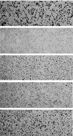
Figure 1: Photomicrographs (100x) show the microstructure of five Ultrafine grades from different manufacturers. The dark spots are pores and the light areas are particles. The microstructure is a very important factor in the ability to resist wear.
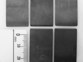
Figure 3: Corner wear of five electrodes used for finishing cut, identical machine parameters. Each material is classified as an Ultrafine material by the manufacturer. The ability to resist wear at the corners by grade.
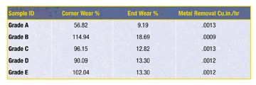
Table 2: Thin rib finishing cut with graphite grades in Ultrafine classification from five manufacturers featuring 06 tool steel, 220 volts open to the gap, two amps peak current, 12 microseconds on-time and two microseconds off-time.
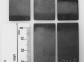
Figure 2: Corner wear of five electrodes used for roughing cut, identical machine parameters. Each of these materials is classified as an Ultrafine material by the manufacturer. The ability to resist wear at the corners varies by grade.
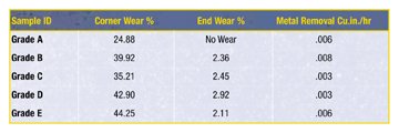
Table 1: Thin rib roughing cut with graphite grades in Ultrafine classification from five manufacturers featuring 06 tool steel, 80 volts, six amps peak current, 25 microseconds on-time, four microseconds off-time and .200" depth of cut.
Electrode wear - is understanding it really important? Often, it is the application that is the deciding factor in whether or not electrode wear is important to the job. If the job is a large cavity without critical dimensions and a fast metal removal rate is the goal, then electrode wear will not be as important as it would be to a job with intricate detail or thin, deep ribs. However, it is still important to be aware of how and why electrode wear occurs in order to achieve maximum EDM efficiency.
What Causes Wear
The EDM process is best described as thermoelectric - heat and electricity acting together. The current passes through the electrode to the work metal. When the electrical energy discharges, it ionizes a path through the dielectric fluid and vaporizes an area on the work metal.


Graphite particles are bound together by chemical and mechanical means. The voids between these particles can be designated as the pore structure. These pore walls represent the interface between the particles and are the weakest part of any graphite system. As the heat destroys this structural interface, particles are lost from the working surface of the electrode. The amount of particle loss is the graphite wear that will determine the accuracy of the cut, the surface finish of the cavity and the stability of the cut. The material loss is more significant with large grain graphites since the amount of wear will be greater than with small grain graphite at the same operating parameters. As a result of this wear, large graphite particles may fall into the gap and can cause arcing in manual machines or reduced speed due to instability of the cut. Machines with automatic sensing could be slowed considerably as they attempt to keep the gap clear. Graphites with a consistent microstructure of uniform particles and pores will resist wear and perform better than graphites with large, irregular particle and pore structures.
There are several methods to reduce electrode wear. It is impossible to eliminate all electrode wear caused by the thermoelectric process, but it can be minimized under specific operating parameters and it can be controlled by the microstructure of the graphite used for the electrode material.
Electrode Wear
There are three types of electrode wear - end, corner and side wear. End wear is the simplest form of wear and is defined as the reduction in length of the electrode during the EDM process. End wear is the only type of wear that can be controlled by the operating parameters. Corner wear and side wear are controlled by the material's ability to resist wear.
End Wear
In the EDM process, sparks are produced on the leading edge or working surface of the electrode as it approaches the work metal. The amount of end wear is a factor of the machine settings and the material's ability to resist wear.
With many work metals, it is possible to reduce the amount of end wear to one percent or less by adjusting the on-time. The exact parameters will vary according to the particle size of the graphite material, but long on-time and positive polarity are necessary for a no-wear condition (less than one percent).
This no-wear condition is actually the result of metallics and carbon plating onto the face of the electrode. This plating phenomenon, caused by extended on-times, must be of a sufficient rate to overcome the vaporization rate of the graphite particles in order to produce the "no-wear" effect. Too much plating action will cause the electrode to grow. This growth may lead to nodules forming on the end of the electrode and distort the shape of the electrode. No-wear settings do not produce the fastest metal removal rates, but they do conserve the electrode.
Some electrode/work metal combinations cannot be put in a no-wear condition, such as tungsten carbide and copper alloys. It also is important to remember that no wear applies only to end wear, not to corner wear or side wear.
Corner Wear
Depending on the shape of the electrode, corner wear can be the most important wear characteristic. The most vulnerable points on the electrode will be the corners and sharp angles. Corner wear is controlled by the graphite's ability to resist wear, which will determine the degree of accuracy of the final cut. The corners are subjected to greater wear because more sparks are generated in this area, thus creating more heat buildup. This effect becomes greater as the sharpness of the angle increases. To minimize the corner wear, graphite should have a uniform microstructure of small particles and pores, combined with high strength.
If extra stock has been left on the electrode so that it can be redressed as needed, the amount of corner wear will determine how many times the electrode can be successfully redressed. The electrode must be dressed back beyond this worn area.
Side Wear
Wear along the side walls of the electrode will cause the cut to taper as the depth of cut increases. Side wear is caused by graphite particles eroding away from the electrode, causing mechanical abrasion from this debris passing along the side of the electrode as it is flushed out of the gap. Poor flushing condition, large particles or excessive particles in the gap can cause sparks to bridge the gap and increase the amount of overburn or slow down the speed of the cut.
There are several ways to avoid this. For example, orbiting an undercut electrode greatly reduces the side wall taper of the workpiece; produces more even side wear on the electrode; and allows particles to escape the gap. Reduction of particles in the gap can be controlled by the graphite's ability to resist wear, and removing particles from the bottom of the cavity can be accomplished by vacuum flushing.
No-Wear EDMing
How do you put your electrode into a no-wear situation if the goal is to conserve the electrode? The key factor to a no-wear condition is the length of the on-time. Since the length of the on-time is dependent on the particle size of the graphite, it is very important to know the properties and characteristics of the graphite grade. Selecting a no-wear condition from the machine menu may not approach the desired no-wear condition since these preset parameters are based on graphite in general, not the specific grade that is being used. The parameters may need to be set to a more aggressive on-time to put the electrode in a no-wear condition. The graphite manufacturer may be able to recommend parameters for a particular application or it may have published performance charts that show the parameters necessary to achieve a no-wear situation.
Longer on-times also will increase the amount of overburn, but undercutting the electrode can control this.
Grade Selection Within a Classification
When it is not possible to put the electrode in a no-wear condition, the selection of the proper grade of graphite can reduce the amount of wear. Since each manufacturer produces many grades in a number of classifications, it is important to understand the characteristics of the graphite. For example, there are many grades in the Ultrafine classification (less than five-micron particle size) and the microstructure of each will determine its wear characteristics.
When you examine some of these graphite grades under a 100x magnification, you get a real view of graphite structure and particle/ porosity relationships. Grades within the Ultrafine classification can have an average porosity as large as 2.3 microns or as small as .9 microns. When the pores become smaller and evenly distributed - as they do with the higher strength Ultrafine grades - then the end wear and corner wear rates are improved.
Examine the 100x photomicrographs of some Ultrafine grades (see Figure 1). The dark regions in the photos represent the pores while the lighter regions represent the graphite particles. Clearly, there is a difference in the structure of these materials, which will result in a variance in strengths, machinability, surface finish and, ultimately, the wear resistance.
Graphites with large, irregular particles and pores wear more quickly than graphites with small particles and pores. Material with rounded particles tends to pack more efficiently - leading to higher strengths that can resist wear longer than material with irregular pore/particle structures.
Selecting Graphite by Grade
Thin ribs are just one application where electrode wear can be a significant factor in the overall job. Flushing is difficult in the slot due to the size of the electrode and cavity being produced. Excessive electrode wear will make it harder to keep the gap clear for efficient cutting and to make an accurate cavity.
Although thin rib electrodes are generally produced from graphite in the Ultrafine classification, expect the performance to vary depending on the manufacturer and the grade selected. Comparison data shows how the performance varies from grade to grade within the Ultrafine classification.
Graphites from five manufacturers were machined into ribbed electrodes .025" x .75". The ribs were burned into 06 tool steel without flush or programmed jump cycle. Two specific and quite simple conditions were selected. The first condition was a roughing setting at six-amp peak current to verify metal removal rates and indicate possibilities for instability at lower (80 volts) voltages. The second condition at two amps peak current and 220 volts was intended to provide corner wear and end wear results at "finish" type conditions. Surface finishes were not measured, as orbital movements or multiple low amperage settings were not included. All measurements were derived from an average of two burns per condition. Tables 1 and 2 indicate the EDM parameters used and the results generated from the individual cuts.
The results in Table 1 demonstrate the performance variance between the grades. At six amps, the on-time was sufficient to yield respectable metal removal rates for all of the tested grades while yielding from zero to 2.92 percent end wear. This represents a 192 percent variance in end wear rates. Corner wear followed suit at 24.88 percent on the low end and a high of 44.25 percent, resulting in a total variance of 78 percent on corner wear at the six-peak amperage setting. These cuts also indicate a slightly higher metal removal rate for the grades with a larger particle size (see Figure 2).
Finish cuts exhibiting higher wear rates - related to reduced amperage and on-times - are shown in Table 2. Since the object of a finish cut is to produce a particular surface finish in the work metal, the metal removal rate is minimal (see Figure 3).
The two-amp peak current setting yields metal removal rates averaging .0012 cu. in./hr. Corner wear rates were typical of low amperage parameters with a low of 56.82 percent to a high of 114.94 percent. The lower amperage testing also shows an end wear increase as predicted and was recorded from as low as 9.19 percent to a high of 18.69 percent. This represents a substantial variance of 103 percent on both end wear and corner wear rates on the Ultrafine grades that were tested. Photos of the electrode corners after use shows minimal corner wear to pronounced rounding of the corner between the various grades of graphite.
In summary, the test results indicate considerable EDM performance variations within the Ultrafine classification of EDM graphites. All of the materials were capable of producing stable cuts without flushing at the stated parameters with varying amounts of electrode wear. As evidenced by the variance in wear-rate performance at the two-amp peak current level, the importance of graphite structure and strength becomes even more evident. An Ultrafine material with high strengths and uniform particle/ pore distribution may allow the job to be produced with fewer finishing electrodes. These higher strength materials can reduce electrode fabrication difficulties such as chipping; help eliminate wire breakage in wire EDMing of graphite electrodes; and provide an overall reduction in graphite costs and usage.


Related Content

Small, Agile Mold Builder Keeps Speed and Accuracy at the Forefront
Michigan-based Zero Tolerance tests the limits of moldmaking and molding with teamwork and technology that permits changes on the fly.
Read More
Mold Builder Meets Increased Domestic Demand With Automated Cells
Burteck LLC experienced significant demand increases due to reshoring and invested in automated machining cells to step up its production output quickly and avoid losing business.
Read More
Advantages and Disadvantages of Copper and Graphite Electrodes
Both copper and graphite provide approximately the same end result, so it is important for a shop to consider the advantages and disadvantages of each material in order to discover what would work best in their shop floor environment.
Read More
Five-Axis Graphite Mill With Automation Debottlenecks Electrode Machining
Five-axis electrode cutting enabled Preferred Tool to EDM complex internal screw geometry on an insert that otherwise would have had to be outsourced.
Read MoreRead Next

Electrode Effect on a Quality EDM Finish
The production of fine surface finishes in the cavity does not come with the technological improvements of the EDM sinker unless an electrode material of higher quality is used.
Read More
Are You a Moldmaker Considering 3D Printing? Consider the 3D Printing Workshop at NPE2024
Presentations will cover 3D printing for mold tooling, material innovation, product development, bridge production and full-scale, high-volume additive manufacturing.
Read More
How to Use Continuing Education to Remain Competitive in Moldmaking
Continued training helps moldmakers make tooling decisions and properly use the latest cutting tool to efficiently machine high-quality molds.
Read More