
It’s Time to Reevaluate Co-Injection Technology
With the development of new resins, hot runners and controls technology, co-injection is positioned to move from a niche market application to mainstream acceptance in the upcoming years.
Recently, there has been a re-emergence of interest in co-injection technology spurred on by the development of new resins, barrier systems, controls and hardware technologies.
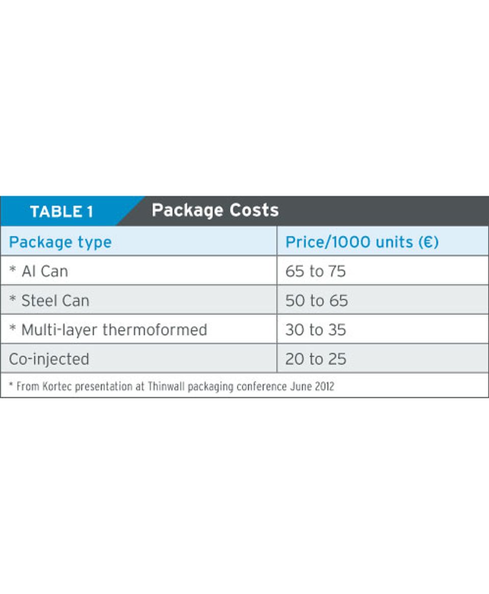
Injection molded parts for the packaging marketplace could cut the costs of a barrier packaging by 30 to 50 percent.
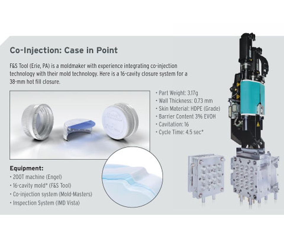
Co-Injection Case in Point: F&S Tool (Erie, PA) is a moldmaker with experience integrating co-injection technology with their mold technology. Here is a 16-cavity closure system for a 38-mm hot fill closure.


Historically, co-injection workcells have been highly specialized, dedicated systems with a high capital cost. Now there are new solutions coming on the market, which allow moldmakers and molders to create co-injection systems at a radically different cost because they are now able to use their existing machines and standard molds for the solution.
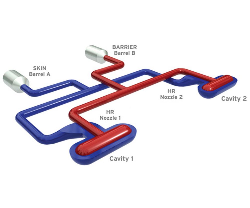
Co-injection is the process of injecting two resins simultaneously through a single gate to form a multi-layer structure. This advanced molding technique has been used for a couple of decades with some success in specialized applications like ketchup containers, stadium beer bottles and medical vials. However, recently there has been a re-emergence of interest in co-injection technology spurred on by the development of new resins, barrier systems, controls and hardware technologies.
Target Markets
There are a number of target markets that would benefit from the advancement of co-injection technology. In general, there is a high demand for shelf-stable products for packaging products such as sports drinks, carbonated beverages, condiments, chemicals, medical, fruits, coffee, pudding cups, spreads, tea, beer, wine, dairy, soups, baby food and pet food. The market for preserved food represents a volume of 16B units per year, according to Euromonitor International (report published in 2012).
These markets have traditionally been served by glass, can and multi-layer thermoforming products, but the market is hungry for the advantages that an injection molded part could give.
The great benefit of injection molding is the production of a net part in a single operation, eliminating secondary operations, handling, assembly, scrap or other costs.
Injection molded parts for the packaging marketplace could cut the costs of a barrier packaging by 30 to 50 percent (see Table 1). The cost of a barrier closure could be reduced by more than 50 percent, compared to the traditional three-piece system with liner and foil.
Additional benefits for an injection molded part are the reduction in energy to create the package, the elimination of thermoforming scrap, and the opportunity for brands to create unique brand identity with the freedom of design, which injection molding allows.
The Co-Injection Workcell
There have been a couple of key advancements on the resin side to create better co-injected parts. First, barrier resins (typically EVOH and Nylon) have evolved over time to be more stable and more compatible with skin resins such as PP, HDPE, PET and PC. Secondly, new adhesives have been developed to help bond the dissimilar skin and barrier resins.
So what differentiates the newest co-injection systems from a standard injection molding workcell? A state-of-the-art co-injection workcell contains many of the same elements of a traditional workcell with additional flexible elements, which can be transferred between cells for future projects and applications—a standard molding machine, standard cold-half, secondary injection unit, a co-injection sequence and process controller, co-injection hot runner and an optional barrier inspection system. Below are some key considerations for these co-injection-specific pieces of equipment.
Secondary Injection Unit
The secondary injection unit can be integrated with the machine or standalone. The decision is based upon flexibility and your application. If you are looking for flexibility or if you have a dedicated workcell for this application, you may want the benefits of an integrated two-shot machine equipped with a single HMI, a single control in which everything is more tightly integrated. A standalone unit will have a separate controller, but it gives you a few benefits such as the flexibility to move the system from machine to machine; typically a quicker delivery and a standalone system solution can be less expensive.
Standard Cold-Half
No major changes to the cold half of a mold are required for co-injection versus mono-layer injection because one material is inside another as opposed to a two-material application that requires movement and complexity within the tool in order to allow the second material to be overmolded on the first. With co-injection you have a finished part when the mold opens the first time. In any other two-material process, you will have some sort of insertion rotation, slide, etc.
Co-Injection Sequence and Process Controller
The key for successful co-injection molding is the design of the hot runner system and the control of the process via the process controller. Specifically, co-injection requires very precise dosing of the barrier resin relative to the skin. This requires a controller capable of real-time, closed-loop control of two injection units, hot runner temperature controllers and valve gate movement during an injection time of as little as 0.2 to 0.5 seconds.
There are two elements to control: (1) control of sequence, which is fundamental to co-injection working; and, (2) in order to control that sequence, it is critical to control the temperature to a more accurate degree.
You cannot use a machine-based temperature control, which is typically an on/off type of control. You need a faster reacting control in order to be able to quickly respond to changes in each of the nozzles to keep the system balanced. It is fundamental that the system be highly balanced during fill in order to make the barrier fill equally in all cavities.
The complex control elements are hot runner temperature control, valve gate sequencing and positioning, sequencing of the injection unit, the second injection unit and the coordination of the primary and secondary injection units. Typically all of these functions have their own separate controller, but for co-injection these must all be integrated through a single HMI.
The automated control logic should display all four of these elements on a single screen for the operator to be able to see what is going on very quickly and understand the process. Using separate controllers makes process control almost impossible.
Imagine an operator on the floor on a standard system. They would have a temperature controller, the controller separately with its own screen, the valve gate controller with a separate screen, the first injection unit on the normal machine HMI, and then the second injection unit with its own HMI. For a molder to interface and coordinate all of this is nearly impossible. That is why it all needs to be integrated.
This challenge is what drove the latest innovation in co-injection technology—enabling integration into a single control with all of the relevant details on a single screen that could allow anyone to run the machine.
Co-Injection Hot Runner
Within the hot runner, the keys to success are the nozzle design for merging the barrier and skin layers as well as the precise and balanced filling of the mold. Without a very balanced fill profile in all cavities, co-injection technology will be limited to small cavitation applications.
There is a specialized nozzle design required. A standard nozzle or an unbalanced manifold system should not be used. It has been found that it is critical to use a two-piece braze manifold technology, or the like, to get the highest level of balance. The point is you have to be highly attentive to fill balance.
For ease-of-service, the hot runner must be designed to be serviced like a standard hot runner system, so that existing injection molding technicians can understand and service these systems. For example, it must have interchangeable thermocouples, removable nozzle tips and seals for in-press servicing that is similar to traditional servicing processes of mono-layer hot runners (e.g, how to remove a valve pin, a nozzle tip, etc. ). This results in more effective training of service technicians working on co-injection hot runners.
The key to success here is the more you can make co-injection like the standard mono-layer process, the better the success rate will be.
Barrier Inspection System
A barrier inspection system (optional, depending on the part requirements) is typically on larger cavitation systems. For cavitations of eight or less the system may be accurate enough to be able to detect if the barrier has been injected or not, thus eliminating the need for inline inspection.
For larger cavitation systems, it becomes increasingly important to use inspection because if you don’t inject barrier into one of 96 positions, it is impossible to detect via the screw position in the injection unit.
On small cavitations, if you did injection barrier into all cavities equally, the hold position on the injection unit would change slightly and you would be able to analyze that on the controller and determine that you didn’t make a good part.
Part Design
There are some part designs that are more successful than others for co-injection. For example, it is advisable to have no drastic changes in wall sections along the flow path, as this can affect the barrier filling profile. There should be no holes in the part that the barrier needs to flow around and no large ribs in the flow direction, as these act as flow leaders that advance the barrier flow. For example, stack shoulders are better than stacking ribs. (Note that ribs, which are transverse to the flow direction, are fine and generally do not affect the barrier fill profile.)
Parts with similar flow distance to the parting line are ideal, but oval, square and rectangular can be filled successfully also. Parts should have a 2- to 4-mm lip or land area where the barrier can fill into at the end of the fill that allows for some variation of barrier flow front. For example, the lip of a container or the TE band on a closure.
Mold Design
Part design and mold design are closely connected, so any part design changes will affect the mold design slightly. When it comes to the mold design you do need to adapt to the gate detail for the co-injection nozzle, which is typically different than standard monolayer gate details.
It is absolutely important that the part-to-part variation is minimized as much as possible through finer tolerances, and also that any core shift from part-to-part will affect the flow of the barrier. Robust tapers and a sturdy stack design are advisable for co-injected parts that would be subjected to core shift.
Summary
Mainstream acceptance of co-injection is key to industry growth, so taking the time to fully understand all of the recent advancements that have been made in co-injection technology is essential. It is no longer cost-prohibitive and focused on highly specialized niche applications. Solutions available today can help moldmakers and molders embrace co-injection within their current operations.


Related Content

Customized CAM Strategies Improve Five-Axis Blow Mold Machining
The proper machining process and workflow can impact blow mold production, making your CAM software selection critical.
Read More
Innovative Mold Building Enhances Packaging Material Efficiency, Elevates Recyclable Design
A manufacturing-focused design and optimized tooling enhance material efficiency in packaging for a new medical instrument.
Read More
How to Solve Hot Runner Challenges When Molding with Bioresins
A review of the considerations and adaptations required to design hot runners and implement highly productive injection molding operations.
Read More
Compact Stack Mold for Thin-Wall Packaging
Oerlikon HRSflow says the patent-pending design allows the use of smaller injection molding machines while still promising the high output a stack mold tool.
Read MoreRead Next

Impact of Hot Runners on Life Cycle Molding Costs
Five factors to consider when selecting your next hot runner solution.
Read More
How to Use Strategic Planning Tools, Data to Manage the Human Side of Business
Q&A with Marion Wells, MMT EAB member and founder of Human Asset Management.
Read More
Reasons to Use Fiber Lasers for Mold Cleaning
Fiber lasers offer a simplicity, speed, control and portability, minimizing mold cleaning risks.
Read More