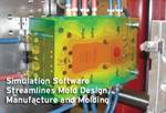
How to Test Mold Design Performance
Simulation can make a company achieve its production goals faster, being more profitable.
In the injection molding industry, it is common for companies to rely on trial-and-error methods to solve production problems. Without process simulation, operators suggest a mold configuration, which “should work” for a specific part geometry, based on experience. Factors such as tempering or processing times are defined later during the first production trials. It is not uncommon to find molds that require several rework stages, as well as parts with quality issues where the causes for these issues are not well understood.
Simulation technology can help avoid all these typical processing problems while saving significant time and effort during the development of a new mold. When utilizing the approach of process simulation all the elements of the mold can be included. This allows the molder to run a virtual production—including all the process stages (preheating of the mold, injection and curing) not only over one cycle, but over several production cycles. With this process, the performance of a mold design can be evaluated completely before the steel is even cut.
Historically, molders have relied on conventional injection molding tools to predict the filling of the cavity. Many processors still think this is all simulation can do for them. However, simulation tools available nowadays are far more powerful. Besides filling, the curing reaction can be accurately predicted, and the thermal behavior can be exactly anticipated.
Simulation can make a company achieve its production goals faster, being more profitable.
It can analyze different variables of the design of a new mold. After determining the desired geometry, the process starts with the selection of the injection point or gate type. Understanding the flow behavior, as well as quality issues related to weld lines, air gaps or jetting, the runner geometry can be defined. In this stage, different aspects including cavity balance or the pressure requirement can be predicted.
Once the part and runner are defined, the tempering of the mold can be designed. In the simulation, the tempering elements can be precisely included: it is possible to define their exact location in the mold, as well as the material and the electric power. Even the control system can be defined. Instead of assuming a mold temperature in the simulation, the exact thermal condition of the mold is predicted, including the way it fluctuates over time.
After the effect of the desired tempering system is simulated, factors in the mold that can compromise part quality can be identified. Cold spots in the mold where the material cures too late or irregular temperature distributions, which can produce different curing degrees for parts produced in different cavities, are some examples of the virtual troubleshooting that can be achieved with process simulation.
Related Content
-
The In's and Out's of Ballbar Calibration
This machine tool diagnostic device allows the detection of errors noticeable only while machine tools are in motion.
-
How to Generate the Ideal Tool Path for High-Level Accuracy and Finish
When a mold builder can’t compromise part accuracy and surface finish, CAM software with specialized programming strategies is essential.
-
Tolerancing in Mold Design, Part 1: Understanding the Issues of Conventional Bilateral Tolerancing
Mold designers must understand the location, orientation and form limitations of conventional tolerancing before changing to another dimensioning system.


.jpg;maxWidth=300;quality=90)

