
How to Design Hot Runner Plates
Moldmakers are often required to design and make hot runner plates for molds. Being aware of these best practices can make the process easier.


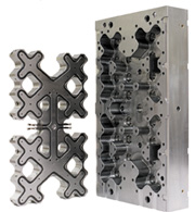
Figure 2: Manifold plate with integral pocket.
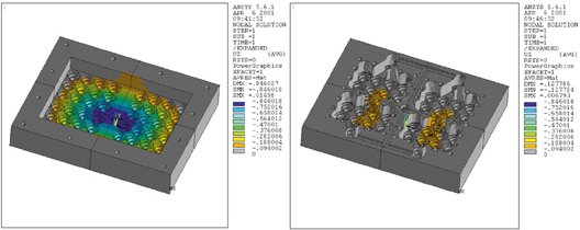
Figure 3: Deflection comparison of contoured and rail plate design. Both designs assume the same sealing force. Under these conditions, the rail design has a manifold plate deflection of 0.033" compared to 0.005" for the contoured plate design with pillars.
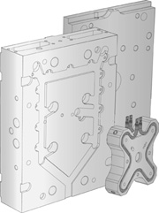
Figure 1: Exploded view of hot runner showing plates.
Proper design of the hot runner plates is critical to molding success. The hot runner plates must perform the function of a rigid and stable support while being exposed to high mechanical loadings from both the hot runner components and the molding machine. Hot runner plates consist of a manifold plate and backing plate that when attached together form the structural shell of the hot runner system (see Figure 1). As an integral part of a successful hot runner, the design and manufacture of the hot runner plates deserves discussion.
Hot runner systems utilize thermal expansion to develop a sealing force between components. The sealing force is created when the bond between the manifold and backing plate resists yielding to the thermal expansion of the manifold components. The sealing force must be sufficient to prevent plastic leakage at maximum machine pressures and can exceed 12,000 lbf for each nozzle. Additionally, hot runners for high cavitation molds utilize cross manifolds, which can add as much as 80,000 lbf to the forces working to separate the plates.


Clamp tonnage and forces from the machine nozzle also act on the hot runner plates and must be considered when designing the plates. Clamp tonnage is transferred through the hot runner plates to the parting line. The hot runner plates must both protect the internal manifold components from the cyclical forces of clamp tonnage and resist deflection that can wear the mold components. Additionally, other forces acting on the manifold include the machine nozzle and the plastic pressure - both of which act along with the sealing force to separate the manifold and backing plate.
Manifold Plate Design
The manifold plate has three main functions - support and align the hot runner components, provide surface area for backing plate bolting, and back-up the cavity plate and its components. Manifold plate design must consider these three functions for successful operation.
Plastic melt travels from the machine nozzle to the gate through precisely aligned melt channels. Misalignment of the melt channels can cause any number of problems - from poor color change and burning to complete leakage and flooding of the hot runner. Manifold plate design must provide suitable support for the components responsible for alignment. These components include locating insulators, installation bolts and nozzles. Plate manufacturing also must utilize tools and methods that can maintain the tight tolerances required for these components to function properly.
Robust attachment of the manifold and backing plate is critical to resist the separation forces discussed above. There are two approaches to the design of the manifold plate relative to how it will be attached to the backing plate. One approach is to use a single plate to support the manifold and nozzle components. The backing plate is then attached with rails mounted around the manifold. The rail style provides for uncomplicated plate design and manufacture; however, it jeopardizes the integrity of the nozzle seal by limiting bolting to the outside of the manifold.
The second method is to cut a contoured pocket that mirrors the manifold into a single plate (see Figure 2). The benefits of this contoured pocket design outweigh the increased complexity for manufacture. Following the outline of the manifold, the pocket makes more surface area available for attachment to the backing plate. Backing plate bolting can then be placed close to the center of the plates and near the nozzles where separation forces are greatest. The increased mating surface area - compared to the rail design - provides improved resistance to deflection under loads from clamp tonnage. Additionally, fewer bolts breaching the manifold plate permit a better cooling circuit design with fewer limitations.
Pillars should be designed in the plates wherever sufficient space through the manifold is available. Whether the plate is designed with rails or as a contoured pocket, pillars can provide significant resistance to plate deflection by allowing bolting near the areas of greatest stress. Pillars can be bolted on or integral to the manifold plate. The pillar has sufficient surface area to resist stress cracking from the bolt threads and to reduce the risk of hobbing into the plates. Integral pillars also should have a radius at their base to reduce stress concentration. Like the rails, pillars that are bolted through the manifold plate also can affect locations for water lines in the plate.
The manifold plate also provides support to the cavity plate and in many cases it is the direct back-up to the cavity inserts and other mold components. Design of the manifold plate must consider the location and requirements of the cavity plate components. Wire channels must be located away from leader pins and cavity inserts that require a solid back-up.
Heating and cooling of the manifold can result in the generation of condensation in the manifold pocket. Water trapped in the manifold plate can cause corrosion and reduce the life of the hot runner components. Condensation channels should be provided in the manifold plate to allow condensate to drain from the pocket.
Backing Plate
The backing plate supports the hot half of the mold to the stationary platen. The backing plate contains the clamp slots, mounting bolt locations or quick mold change geometry required to mount the mold to the stationary platen. In addition, the backing plate may contain air or hydraulic lines for a valve-gated hot runner.
The functionality of the backing plate hinges on how well it is secured to the manifold plate. Ideally, plate bolts are located near each drop to oppose the plate separation forces generated by thermal expansion. It is recommended that for systems with two to eight drops, three bolts should be positioned at each drop, forming a triangle. Triangulation places an even force on the components and prevents distortion. On larger systems, a shared bolt pattern is necessary due to space limitations. It is critical during assembly of a hot runner system that the backing plate bolts be torqued from the center of the plate. This will prevent the plate from bowing and allow it to sit flat on the manifold plate.
Plate Deflection
Injection molding machine manufacturers dedicate large amounts of resources to designing and developing platens with flat surfaces and minimal deflection. Platen or plate deflection can lead to non-uniform pressure distribution across a mold face, resulting in core shift and ultimately leading to poor part quality.
Hot runner plate design has a direct influence on the resistance to plate deflection caused by the forces required for proper sealing (see Figure 3). The features discussed here - single plate with manifold pocket outlining the manifold and pillars - reduce manifold plate deflection by 86 percent under maximum forces on a 48-cavity hot runner. Although the single plate design is subject to higher separation forces, due to the cross manifold, the tighter bolting pattern and pillars greatly reduce the tendency for plate deflection.
Plate Cooling
The hot runner plates should include cooling lines to reduce wear and stabilize the plate temperature. Proper cooling in the hot runner plates prevents the transfer of heat to the mold or the machine platens. In the absence of cooling, plate heating also can reduce the sealing force and, through thermal expansion, cause misalignment of mold components. Also, heat generated by the hot runner can heat the machine stationary platen. Non-uniform heating of the machine platens can lead to premature tie bar wear.
Ideally, the cooling circuit should run in close proximity to the locations where the heated components contact the plates. This allows the heat conducted to the plates by contact of the components to be removed efficiently with minimal thermal expansion. Additionally the cooling circuit should be balanced within the plates to maintain a uniform temperature distribution throughout the plates.
Plate Material
Hot runner plates are manufactured from either a stainless steel or P20. The corrosion resistance of stainless steel adds value to the plates by extending life. Hot runner plates are in close contact with both water vapor and potentially corrosive off-gassing from heated plastics.
Conclusion
Hot runner plates play a major role in the performance of the mold. Along with supporting the hot runner components, the hot runner plates can impact mold life and the quality of the molded product. Poorly designed plates can lead to damaged cores, worn slides and vents and ultimately higher costs to keep the mold in operating condition. It is important to the mold designer and processor to understand the function of the hot runner plates and the design options that need to be considered.


Related Content

Revisiting Some Hot Runner Fundamentals
What exactly does a hot runner do? If you’ve been in the injection molding industry for any length of time, you might think the answer is obvious, but it is not.
Read More
Maintaining a Wire EDM Machine
To achieve the ultimate capability and level of productivity from your wire EDM on a consistent, repeatable and reliable basis, regular maintenance is a required task.
Read More
What You Should Consider When Purchasing Modified P20 Steel
When buying P20 steels that have been modified, moldmakers must be aware of the variations and key issues that affect delivery, cost and lead times.
Read More
Laser Welding Versus Micro Welding
The latest battle in finely detailed restoration/repair of mold materials.
Read MoreRead Next

How to Justify Your Hot Runner Purchase
Four questions to help with hot runner justification.
Read More
Reasons to Use Fiber Lasers for Mold Cleaning
Fiber lasers offer a simplicity, speed, control and portability, minimizing mold cleaning risks.
Read More
Are You a Moldmaker Considering 3D Printing? Consider the 3D Printing Workshop at NPE2024
Presentations will cover 3D printing for mold tooling, material innovation, product development, bridge production and full-scale, high-volume additive manufacturing.
Read More