
High-Speed Milling Guidelines for Hardened Tool Steels
Experiments and observations on high-speed milling from the ERC/NSM at The Ohio State University help shops understand that a complete engineering of the process


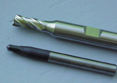
This photo contrasts a general-purpose end mill geometry with that of an end mill specifically designed for high-speed milling hardened tool steels.

Figure 1: Helical interpolation into a cavity using an inserted face mill.

Figure 3: Shanks of end mills should be relieved for cutting tall and thin walls.

Figure 2: Comparison of a theoretical (left) and real cutting edge.

Figure 4: Every system exhibits a tendency that can be represented by stability lobes.
In a survey of die and mold manufacturers in 1995, the question was asked, "What are the most important technologies in die and mold manufacturing in the next two years? Reliable toolpath generation software (CAM) won first place with 61 percent. High-speed milling of hardened die steels was second choice at 49 percent. Since then, it has gained more acceptance in the industry.1 The following observations from the Engineering Research Center for Net Shape Manufacturing (ERC/ NSM) at The Ohio State University may be useful to shops contemplating getting into high-speed milling.
Eliminate Fully Engaged Situations
Fully engaged situations occur when sharp changes of direction are programmed in the cutter path. It is best to add small arcs where corners are to be machined. A typical 90-degree turn without an arc causes the machine tool to slow down too much - decreasing chip load and causing a momentary rubbing action that heats up the tool. At the same time, the tool engagement angle increases from a steady 10 to 15 degrees to approximately 90 degrees - increasing the load on the tool. ERC/NSM experiments show that even a programmed radius as small as 0.005" makes a big difference in maintaining a steady milling regime. There also are dynamic effects when a cutter engages the corner of a pocket - such as the number of inserts in the cut being drastically changed. This in turn affects the tooth passing frequency, and consequently, the stability of the cutting system.


Use Helical Interpolation to Ramp Down Into a Cavity
Helical interpolation helps maintain a steady load on the tool, which improves tool life, as well as surface finish.2 This technique also can be used for roughing cavities. The key is steady, uniform load on the tool. High-speed milling is less tolerant of sudden changes in tool loading. Figure 1 shows an inserted face mill in helical interpolation Due to the helical nature of the path, tool entry will be smooth. Tool loading will smoothly increase to a maximum and stay there during the cut.
Select Cutting Parameters by the Numbers
Do not rely on old conventional milling parameters with which you may be familiar. High speeds for milling of tool steels range from about 1,500 to 3,000 sfm. Always consider the actual "sharpness" of your tool. Typical tool edge radius (sharpness) varies between 0.0002" and 0.0004"; therefore, realistic chip loads should be a minimum of 0.0010". Considering tool diameters, heat generated, etc., maximum chip load should probably be less than 0.010". Figure 2 shows two cutting edges, one theoretically sharp, the other only "real world" sharp. In order to get under the material, our chip load should be larger than the expected sharpness of the cutting edge.
Choose Plain Inserts When Using Inserted Tools
Inserts with chip breakers tend to be more fragile. In our tool life experiments, inserts with flat rake faces (strongest) performed best. It is important to choose those tools and inserts that were specifically designed for high-speed milling of hardened tool steels.
Use Tools with Minimal Flutes
Tools with minimal flutes are stronger as well as more rigid. Traditional end mills usually have deeper flutes and are thus less rigid. During high-speed milling we will be taking lighter cuts and creating fewer chips per rotation of the tool. Deep flutes won't be necessary or useful; instead, rigidity and dynamic balance are more important. Photo 1 contrasts a general-purpose end mill geometry with that of an end mill specifically designed for high-speed milling hardened tool steels.
Use the Right Toolholder
Toolholders that use set screws are not suitable because they are inherently unbalanced. Even collet toolholders are thought to be unsuitable past 10,000 rpm. Toolholders with hydraulic chucks are the accepted norm between 10,000 and 20,000 rpm. Higher speeds demand shrink fit and balanced tooling for best results.
Relieve the Tool
It is important to relieve the tool when machining thin-walled parts. One should machine the most flexible region of the workpiece first and then work toward the less flexible or fixtured areas. Once the most flexible region is cut, it is important that it does not come in contact with the tool again. This is best accommodated by relieving the tool (see Figure 3).
Consider Cutting Dry to Improve Tool Life
Milling, by its very nature is an "interrupted" process. The cutting edges of a milling tool go in and out of cut all of the time - heating up within the cut and cooling down outside of the cut. High-speed milling generates higher temperatures than conventional milling. Typically, casing and other workpiece suppliers coat the surface of the workpiece with a rust preventive oil. During cutting, the oil carries away a lot of the heat, drastically reducing the temperature of the cutting edge. This drastic fluctuation in temperature can cause premature cracking and fracture of the cutting edge, commonly referred to as thermal shock. It is imperative to eliminate such residual oils as much as possible. The same theory applies to cutting fluid. Typical flood coolant usually causes thermal shock to the cutting edges reducing tool life. High-pressure air supplied through the spindle is usually a good choice for clearing the chips away from the cutting zone.
Recognize and Identify Dynamic Stability
Chatter or other vibration-related problems often become the limiting factor in determining how much of the available speed and power can be incorporated into the milling process. Therefore, they are very important when dealing with high-velocity machining. As seen in Figure 4, every system exhibits a tendency that can be represented by stability lobes. A system is stable when the generated chatter frequency is equal to the tooth passing frequency or some harmonic of it. The stability lobes tell the user as to what rpms and depths-of-cut to run the tool so that the material removal rates are maximized.
Some aspects of high-speed milling technology have just been reviewed, but complete coverage is beyond the scope of any single article. It is important to remember that in contrast to conventional milling practice, high-speed milling requires a complete engineering of the process (a systems approach) for success.
References
1"Survey of the U.S. Die and Mold Manufacturing Industry," P.FallBoehmer, Report No. ERC/NSM-D-95-41, July 1995.
2"Tool Materials and Cutting Strategies for High-Speed Machining," J.Fernandez, Report No. HPM/ERC/NSM-98-R-017, February 1998.


Related Content

6 Ways to Optimize High-Feed Milling
High-feed milling can significantly outweigh potential reliability challenges. Consider these six strategies in order to make high-feed milling successful for your business.
Read More
Solving Mold Alignment Problems with the Right Alignment Lock
Correct alignment lock selection can reduce maintenance costs and molding downtime, as well as increase part quality over the mold’s entire life.
Read More
Hands-on Workshop Teaches Mold Maintenance Process
Intensive workshop teaches the process of mold maintenance to help put an end to the firefighting culture of many toolrooms.
Read More
The Benefits of Hand Scraping
Accuracy and flatness are two benefits of hand scraping that help improve machine loop stiffness, workpiece surface finish and component geometry.
Read MoreRead Next

Reasons to Use Fiber Lasers for Mold Cleaning
Fiber lasers offer a simplicity, speed, control and portability, minimizing mold cleaning risks.
Read More
Are You a Moldmaker Considering 3D Printing? Consider the 3D Printing Workshop at NPE2024
Presentations will cover 3D printing for mold tooling, material innovation, product development, bridge production and full-scale, high-volume additive manufacturing.
Read More