
High-Performance Milling with a Tool Engagement Controlled CAM System
It is now possible to increase productivity without increasing cost by using a new milling technique—tool engagement milling.


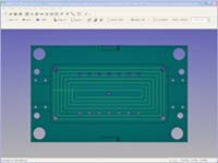
Most CAM systems today use contour offset or parallel offset techniques for generating a toolpath and use high-speed machining (HSM) for cutting pockets in mold bases as shown here. Note the sharp corners where the cutting tool will need to be slowed down to prevent the cutter from plowing into the corner and breaking the cutter. Images courtesy of Surfware.
Tool engagement milling achieves optimal productivity by cutting optimally everywhere. To cut optimally everywhere along the toolpath for any part geometry, it is necessary to control the feedrate, spindle speed, depth-of-cut and the tool’s engagement with the material. This allows for very high material removal rates that have high speeds, feeds and depth-of-cut, resulting in greatly reduced machining time and greatly increased tool life.
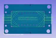
A toolpath that controls the tool engagement will look very different from a contour offset or parallel offset type toolpath. Note that there are no sharp corners and the shape of the geometry doesn’t dictate the flow of the toolpath. Rather, each cut is made such that the next cut can be made at the desired engagement angle.
In today’s highly competitive market it is crucial to underbid the competition and yet deliver a good part at low cost. A key factor in determining the bid price is the machining time. The more quickly the part can be machined, the lower the bid price can be, and the more chance the manufacturer has of winning the job and turning a profit. It is now possible to increase productivity without increasing cost by using a new milling technique—tool engagement milling.
Most CAM systems today use contour offset or parallel offset techniques for generating a toolpath and cut that toolpath with high-speed machining (HSM). HSM uses a high feedrate, but it does not achieve the highest possible productivity. To achieve the highest productivity, not only must the feedrate be high, but the depth-of-cut must be large and the stepover appropriate. HSM cannot achieve this with a contour offset or parallel offset toolpath because when the tool plows into a corner, the load on the tool goes up rapidly and radically. In order to prevent tool breakage and chatter with HSM, a very shallow depth-of-cut must be used. If a very shallow depth-of-cut is used, many passes must be made to cut the part to full depth, increasing the time it takes to machine the part.


Tool Engagement Controlled Milling
The goal of tool engagement controlled milling is to achieve the highest possible productivity. This requires gaining complete control of the cutting environment in order to cut optimally everywhere along the toolpath. To cut optimally means to create chips with the optimal geometry for the particular tool being used and the particular material being cut. This requires controlling the feedrate, spindle speed, depth-of-cut and the tool’s engagement with the material. That is, the highest material removal rate (MRR) can only be achieved when the feedrate is held at its optimal value, the spindle speed is held at its optimal value, the depth-of-cut is held at its optimal value and the tool’s engagement with the material is held at its optimal value (creating the optimal chip).
With tool engagement controlled milling, a machinist only has to know how to optimally perform a side cut with constant stepover, constant feedrate, constant spindle speed and constant depth-of-cut. With this information, a tool engagement controlled CAM system can then create a toolpath, for any part geometry, that cuts everywhere as if it were cutting a simple side cut. This allows for extremely high MRR everywhere along the toolpath, greatly reducing machining time. Cutting chips optimally also greatly increases tool life, greatly reduces the amount of heat created, reduces part warpage, maintains a constant load on the tool, increases dimensional accuracy and entirely eliminates chattering.
Depth-of-Cut
Whereas HSM might use a depth-of-cut of about 0.2 times the diameter of the tool, tool engagement controlled milling can use a depth of cut of 1.5 to 2.0 (or more) times the diameter of the tool. This increase in depth-of-cut allows for far fewer passes to get to the total depth-of-cut, greatly decreasing the time it takes to machine a part. With HSM, only the tip of the tool is cutting. This causes the tip to overheat and wear out rapidly. With tool engagement controlled milling, much more of the flute is used. This allows the load, heat and wear to be spread out evenly over a much larger area of the tool—resulting in much longer tool life.
Chip Geometry Control
Some might have you believe that controlling the material removal rate (sometimes called constant volume milling) achieves the highest possible productivity. This is not true. Controlling the chip geometry, especially the chip thickness, is required to achieve the highest productivity. This can only be accomplished by controlling the tool’s engagement with the material. A toolpath that controls the tool’s engagement with the material and uses a constant feedrate, constant spindle speed and constant depth-of-cut, will by definition have a constant material removal rate. More importantly, it will have a constant chip geometry (including constant chip thickness). This is the key to optimal cutting and high productivity.
Toolpath
In a constant volume scheme without controlled tool engagement, the feedrate must be reduced when the tool encounters a corner, which creates too thin a chip and too much heat. This is especially true for harder materials such as P20 and titanium. This extra heat causes rapid tool wear, which must be overcome by reducing the material removal rate. This problem does not occur with tool engagement controlled milling.
A toolpath that controls the tool engagement will look very different from a contour parallel or direction parallel toolpath. Taking advantage of today’s readily available computing power, it is possible to create a toolpath for which most of the toolpath does not resemble the final shape that is ultimately cut. The entire toolpath is planned in advance such that at no place in the toolpath will the tool engagement exceed the user’s specified value.
A high-end CNC machine is not required to take advantage of tool engagement controlled milling. By reducing the load on the tool, the load on the CNC machine also is reduced and older machines immediately show an increase in productivity.
A tool engagement controlled toolpath allows for consistent cutting everywhere. There are no high pitched squeals as the tool enters a corner. There is no need to attempt to continuously adjust the feedrate or the depth-of-cut. There is no need to have an operator standing by to hit the stop button should something go wrong. There is just smooth, continuous cutting with long tool life. This is ideal for lights-out operation.
Benefits
The productivity benefit from controlling the tool engagement, and thereby controlling the entire chip geometry, is remarkable. Hard-to-machine materials can only be cut well under a narrow range of chip producing conditions. When the entire chip geometry is controlled, a hard-to-machine material becomes easy to machine. With materials such as P20 and titanium, productivity results in excess of two times have been reported by many customers with a simultaneous doubling of the tool life. With soft materials there also is a significant increase in productivity due to the increased depth-of-cut in conjunction with a large controlled tool engagement angle.
Summary
Optimal productivity occurs by cutting optimally everywhere. To cut optimally everywhere along the toolpath for any part geometry, it is necessary to control the feed-rate, spindle speed, depth-of-cut and the tool’s engagement with the material. This allows for very high material removal rates having high speeds, feeds and depth-of-cut, resulting in greatly reduced machining time with greatly increased tool life. This can only be achieved with tool engagement milling.


Related Content

How to Manage Wall Thickness Changes in Your Mold Design
To ensure even filling and cooling, consider wall section transitions, corners and fillets, ribs and bosses, lip and rim designs and CAE flow simulation software.
Read More
Leading Mold Manufacturers Share Best Practices for Improving Efficiency
Precise Tooling Solutions, X-Cell Tool and Mold, M&M Tool and Mold, Ameritech Die & Mold, and Cavalier Tool & Manufacturing, sit down for a fast-paced Q&A focused on strategies for improving efficiencies across their operations.
Read More
Tolerancing in Mold Design, Part 2: Using GD&T to Address Conventional Tolerancing Issues
Mold designers can achieve a single interpretation of workpiece functionality when following the American Society of Mechanical Engineers Geometric Dimensioning and Tolerancing standard.
Read More
Mold Design Review: The Complete Checklist
Gerardo (Jerry) Miranda III, former global tooling manager for Oakley sunglasses, reshares his complete mold design checklist, an essential part of the product time and cost-to-market process.
Read MoreRead Next

CAM for Hard Milling
A brief overview of some of the CAM requirements, challenges and strategies for successful hard milling.
Read More
Reasons to Use Fiber Lasers for Mold Cleaning
Fiber lasers offer a simplicity, speed, control and portability, minimizing mold cleaning risks.
Read More
How to Use Strategic Planning Tools, Data to Manage the Human Side of Business
Q&A with Marion Wells, MMT EAB member and founder of Human Asset Management.
Read More